- Ask a related questionWhat is a related question?A related question is a question created from another question. When the related question is created, it will be automatically linked to the original question.
This thread has been locked.
If you have a related question, please click the "Ask a related question" button in the top right corner. The newly created question will be automatically linked to this question.
Tool/software:
I need to know when the zero (index) pulse of the ABZ input to the QEI is encountered. I can set the SysConfig to generate an interrupt on a Zero event but that interrupt can occur on the zero pulse OR when the counter counts to zero. I need to know the absolute position of my servo system and a false zero or not knowing when zero is absolutely established is a show-stopper. I there a way to isolate the zero pulse from the counter = zero condition?
That does NOT solve the problem. When the interrupt occurs, the counter is always zero (or close depending on how long it takes to service the interrupt). The zero pulse may or may not have been encountered. Note the 2 possible causes of the interrupt in my original post.
You tell me. What I am seeing is that the interrupt appears to occur when the timer counter hits zero. The TRM says the interrupt is on a Zero Event. It does not say whether a Zero Event is the zero pulse or the counter value counting to zero. It appears to be both. A zero event when not in 3 wire QEI mode is when the counter counts to zero.
The intent is to either set a specific position on a knob - knowing where "11" is on a guitar amp - or if you do use it for an index, make the count big enough so that it can never wrap around on its own. That way you know that a zero count is a zero index.
Hi Martin,
In the QEI 3-signal mode, you have the IDX which can generate a load for your timer either setting to 0 or a load value. This would be a 3rd input for your zero pulse. In the initial state you don't know where your position is so to Keith's point making your value so you never cross 0 unless through the zero index is a valid use case.
Regards,
Luke
Maybe I missed it but I see no way to preload the counter value to some on start-up. It seems to start out at the load value or zero, it is difficult to tell. The load value in this case is the value that the counter wraps to when counting down through zero or wraps from when counting up toward zero. So the load value defines the number of bits in the position measurement. If I am correct in this, then there is no way to initially have the counter at a value that is far from zero since the load value is basically -1. I disabled my zero pulse by tying it high and still get the zero event interrupt so my observation about getting the interrupt when the counter goes through zero is correct.
A note: in my case, the counter is 16 bits and I am using all 16 bits so a value out of operating range is not possible. Without being able to positively define the starting point, there is no way to guarantee that the zero index will be encountered when the counter isn't already close enough to zero to not be able to detect the change in SW. If precise absolute positioning is essential, then even a few bits of error could be significant. So I see no SW solution out of this. Of course, as soon as the zero pulse is encountered, the position is correct, but without knowing when the zero pulse has been encountered, the system could lock onto an incorrect position, thinking it has encountered the zero index.
Isn't there some way to 'know' with no ambiguity that the zero index has been encountered without connecting it to a separate GPIO in addition to the zero index input?
You can always do something like this in your init code:
Hi Martin,
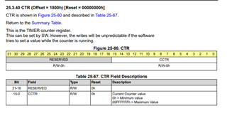
You can write to the Timer's CCTR register and set the counter value then start the timer. So for example if you expect your motor to do 3600 increments in a full rotation, you can set the initial load to 7202, set your timer count to 3601. That way on your initial condition you won't cross into a load or zero on accident, before first receiving a zero pulse. You can then use the shadow load to load your actual 3600 load value and have the zero pulse zero your timer.
The driverlib function for this is DL_Timer_setTimerCount( GPTIMER_Regs *gptimer, uint32_t value);
Of course this is just one idea to handle it, your specific system might need different tuning or you know about better constraints required for your system.

My point above is that I am counting the full range of the 16-bit counter. I have 65536 counts per revolution so there are no unused values since it is only a 16-bit counter in the TIMG peripheral.
I fixed it by providing the index pulse to both the TIMG IDX input and to a GPIO. The IDX input clears the counter. The GPIO generates the interrupt that tells the SW that the index pulse has been encountered. This would signal to the SW the end of a start-up sequence to force the position past zero.
Good solution. I agree that just having the index pulse reset the counter is of limited usefulness, though since there are encoders out there that have it, *someone* must be using it.