This thread has been locked.

If you have a related question, please click the "Ask a related question" button in the top right corner. The newly created question will be automatically linked to this question.

AM2431: GPIO control speed

Part Number: AM2431

Tool/software:

Hi all TI experts:

I am using the AM2431 with FreeRTOS as the system. In one of the threads, I need to control multiple GPIO high/low signals as control signals to manage a peripheral. I am using a for loop to output continuous signals, but I have noticed a longer delay when setting the signal low.

void
my_delay(uint32_t ticks) {
    volatile uint32_t delay;
    
    hGpio1->BANK_REGISTERS[0].SET_DATA = 0x00000400;
    for (delay = 0; delay < ticks; delay++) {
        NOP_DELAY;
    }
    hGpio1->BANK_REGISTERS[0].CLR_DATA = 0x00000400
}

for (scanline = 18; scanline > 0; scanline--) {   /
    for (channel = 16; channel > 0; channel--) {          
        for (driver = 20; driver > 0; driver--) { 
            value = hGpio1->BANK_REGISTERS[0].OUT_DATA;
            
            value |= (((Value1 << 1);
            value |= (((Value2 << 10);
            value |= (((Value3 << 13);
            value |= (((Value4 << 21);
            value |= (((Value5 << 22);
            value |= (((Value6 << 30);
            
            hGpio1->BANK_REGISTERS[0].OUT_DATA = value;
            
            my_delay(delayTime);
        }
    }
}

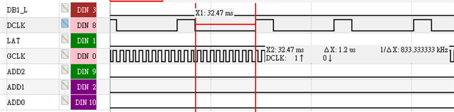
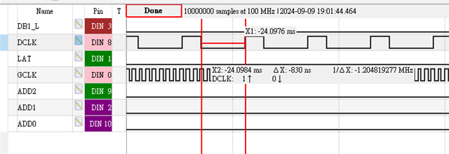
In order to make my GPIO control as stable as possible, I didn’t use vTaskDelay. Instead, I used a for loop with NOP_DELAY inside to prevent the process from switching to other threads. However, I noticed something unusual with the output waveform. I added a GPIO toggle before and after the delay, and by observing this GPIO with a logic analyzer, I found that the low time is almost twice as long as the high time. I didn’t find an option to set the GPIO speed in syscfg, but a simple for loop shouldn’t have this effect. I also tried removing the value operation, but the low time still didn’t decrease. Is there any way to improve this?

best regards,
Larry

  • Hi Larry,

    Thanks for your query.

    Can you please provide more details on the setup?

    . In one of the threads, I need to control multiple GPIO high/low signals as control signals to manage a peripheral.

    How many threads are currently running on the system? What are the priorities of each task?

    but I have noticed a longer delay when setting the signal low

    How are you capturing the waveform?

    Please share the waveform where GPIO is taking longer time than usual.

    Regards,

    Tushar

  • Hi Tushar,

    Thanks for your reply, 

    How many threads are currently running on the system? What are the priorities of each task?

    I have five thread, they are set priority as 

    #define MAIN_TASK_PRI  (configMAX_PRIORITIES-1)
    How are you capturing the waveform?
    Below is my code, I am using a for loop to control the GPIO, and I need to control a total of 12 GPIOs. To save time, I am trying to directly write the desired data into the corresponding GPIO register by matching the required values.
    for (bit = NUM_BITS_PER_CH - 1; bit > 0; bit--) {
    
        gpioTargetValue_0 = hGpio1->BANK_REGISTERS[0].OUT_DATA;
        gpioTargetValue_0 &= ~mask0;
        gpioTargetValue_0 |=    ( (rValue1_l & valueMask[bit])? (1 << UDR1_L_PIN_SHIFT):0 ) |
                                ( (gValue1_l & valueMask[bit])? (1 << UDG1_L_PIN_SHIFT):0 ) |
                                ( (bValue1_l & valueMask[bit])? (1 << UDB1_L_PIN_SHIFT):0 ) |
                                ( (rValue2_l & valueMask[bit])? (1 << UDR2_L_PIN_SHIFT):0 ) |
                                ( (gValue2_l & valueMask[bit])? (1 << UDG2_L_PIN_SHIFT):0 ) |
                                ( (bValue2_l & valueMask[bit])? (1 << UDB2_L_PIN_SHIFT):0 );
    
        gpioTargetValue_1 = hGpio0->BANK_REGISTERS[1].OUT_DATA;
        gpioTargetValue_1 &= ~mask1;
        gpioTargetValue_1 |=    ( (rValue1_r & valueMask[bit])? (1 << UDR1_R_PIN_SHIFT):0 ) |
                                ( (gValue1_r & valueMask[bit])? (1 << UDG1_R_PIN_SHIFT):0 ) |
                                ( (bValue1_r & valueMask[bit])? (1 << UDB1_R_PIN_SHIFT):0 ) |
                                ( (rValue2_r & valueMask[bit])? (1 << UDR2_R_PIN_SHIFT):0 ) |
                                ( (gValue2_r & valueMask[bit])? (1 << UDG2_R_PIN_SHIFT):0 ) |
                                ( (bValue2_r & valueMask[bit])? (1 << UDB2_R_PIN_SHIFT):0 );
    
        hGpio1->BANK_REGISTERS[0].OUT_DATA = gpioTargetValue_0;
        hGpio0->BANK_REGISTERS[1].OUT_DATA = gpioTargetValue_1;
    
        DCLK_EN;
        for (uint32_t delay = 0; delay < universal_config->driver_dclk_delay; delay++) {
            NOP_DELAY;
        }
        DCLK_DIS;
    }
    and I am use LA to capture GPIO signal, here is the waveform, the low state take about 1.2us.
    But if remove two line below, write data into GPIO register,
    // hGpio1->BANK_REGISTERS[0].OUT_DATA = gpioTargetValue_0;
    // hGpio0->BANK_REGISTERS[1].OUT_DATA = gpioTargetValue_1;
    the low state will only cost 830ns,
    Why write data into GPIO registe need 400ns? I don't get it, can I speed up this process?
    Best regards,
    Larry
  • Hi Tushar,

    Any information can share?

    Best regards,

    Larry

  • Hello Larry,

    In the long back, I have captured where one GPIO takes nearly 57nsec for OFF and 43nsec for ON.

    I did not use any APIs to control GPIO ON and OFF and directly write in to the Register address.

    Here, you are using the for loop and logical operations are doing, which also takes some time to process.

    My suggestion is that, based on the above code, you need to control 10 pins directly, then  write either 1 or 0 in the corresponding register without a loop.

    For example, you need to control 31 pin as high. Just set the direct value as 0x80000000 in the register .

    And, if you need to control pins based on some array data, then we can't do anything we have to go for a loop only and make sure that when you, performing this operation any task switching should not happen else this task switching time also should be considered. 

    Regards,

    Anil.

  • Hi Anil,

    I find solution in another discussion, I add MPU in the GPIO address which I want to control, then the speed significantly  improve, thanks for your help.

    Best regards,

    Larry

  • Hello Larry ,

    Did you add a GPIO address to the MPU region and then cached this GPIO address ?

    Can you please share the thread where you got the solution ?

    Regards,

    Anil.

  • Hi Anil,

    Did you add a GPIO address to the MPU region and then cached this GPIO address ?

    Yes, below is my set up.

    Can you please share the thread where you got the solution ?

    https://e2e.ti.com/support/microcontrollers/arm-based-microcontrollers-group/arm-based-microcontrollers/f/arm-based-microcontrollers-forum/1122969/lp-am243-am2434-gpio-latency

    Best regards,

    Larry

  • Hello Larry,

    Thanks for the above link and details.

    I need to confirm these settings with other experts since mostly SOC Peripherals space should be configured to strongly ordered, but here we are configured different configurations and my suggestion is that the size of the above GPIO is at least configured as per TRM.

    For example, the GPIO_0 or GPIO_1 size should be 256 bytes. So, we need to configure the same size instead of 8KB in above MPU configuration.

    Can you please confirm how much latency has improved with the above settings ?

    Did you do this Testing in debug build or release build ?

    If you perform this testing in debug build then perform Testing in release build and see if still performance improved or not as compared to debug build ?

    Regards,

    Anil.

  • Hi Anil,

    Can you please confirm how much latency has improved with the above settings ?

    Before this settings, the low state need 1.2us, after settings, the low state only take 270ns.

    Did you do this Testing in debug build or release build ?

    I test this in debug mode.

    I can test later with release mode, thanks for your helping.

    Best regards,

    Larry

  • Hello Larry ,

    Thanks for sharing the above Results .

    If you do Testing in release mode you may get better results .

    Regards,

    Anil.