Part Number: LP-AM243
Other Parts Discussed in Thread: AM2434
Hi expert,
I modified gpio_led_blink demo code in order to measure the latency for setting GPIO from high to low or low to high. My code is simple.
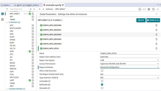
1. manipulate register directly without using device driver.
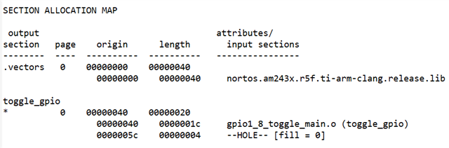
2. put the code to TCMA by add a function to perform toggle infinitely.
void __attribute__((section("gpio_toggle"))) toggle_gpio1_8(void)
{
while(1)
{
*GPIO1_8_SET_ADDRESS = GPIO1_8_MASK;
*GPIO1_8_CLEAR_ADDRESS = GPIO1_8_MASK;
}
}
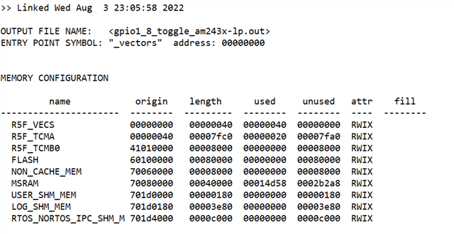
linker command file
GROUP {
gpio_toggle: palign(8)
} > R5F_TCMA
3. set build environment to release mode and change optimize level to fast.
4. program to device and measure it.
Attachment is my project files. I use SDK 8.3
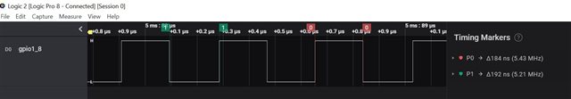
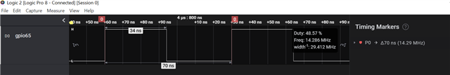
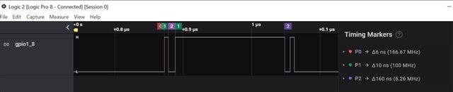
Here are measurement result.
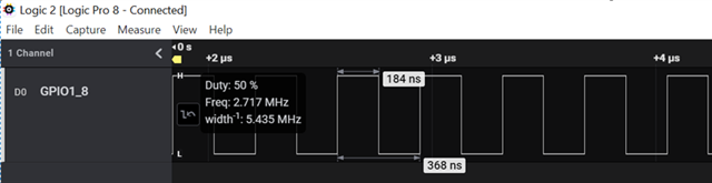
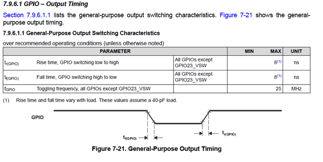
According to the measurement, the latency to toggle GPIO is 184ns but from datasheet.
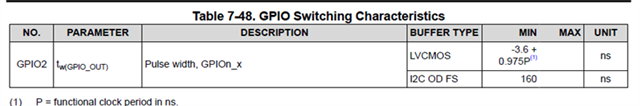
The minimum pulse can be 3.6ns + 8ns * 0.975 FICLK = 500Mhz /4 =125MHz = 8ns.
The gap is huge, may I know is this typical value by using GPIO module to toggle GPIO?
How do we get datasheet result?
Regards
Andre