This thread has been locked.

If you have a related question, please click the "Ask a related question" button in the top right corner. The newly created question will be automatically linked to this question.

AM2434: NIKON Diagnostic Example Code

Part Number: AM2434
Other Parts Discussed in Thread: SYSCONFIG

Tool/software:

Hi,


My customer has some questions about Example code of Nikon Diagnostic in the Motor Control SDK 09.02.00.

-  Should they need some more settings in order to execute the Continuous Mode ?

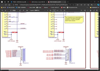
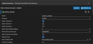
    They configured PRU as Nikon encoder by referring to the program code.

    The encoder communication was able to be started by step by step execution on CCS.

    However, it cannot be started by “RUN” for continuous execution.

    Should they set some Wait on PRU ?

< Execution Result >  

                NIKON firmware  : 0.0.2 (release)

Nikon Single channel, Single PRU Demo application is running......

Channel 0 is enabled

Please enter encoder length connected to Channel 0:

Please enter 1st encoder single turn length: 17

Please enter 1st encoder multi turn length (zero if not a multi turn encoder):
Please enter 2nd encoder single turn length (zero if not connected):
Running CDF4(Multi Transmission command) with maximum encoder address for detecting connected encoder

ERROR: NIKON initialization failed

check whether encoder of selected frequency is connected and ensure proper connections

exit nikon_main due to failed firmware initialization


-  In the use case of “32Start Continuous Mode”, it seems that two parameters (Enter IEP cycle count and Enter IEP trigger time) can be set.

    They tried to change these parameters (3000 – 12000), but they saw no change in the waveform of the encoder communication.

    Could you tell them what these parameters are ?

Related question
https://e2e.ti.com/support/microcontrollers/arm-based-microcontrollers-group/arm-based-microcontrollers/f/arm-based-microcontrollers-forum/1396361/am2434-tamagawa-cycle-time?tisearch=e2e-sitesearch&keymatch=am2434%252520encoder#


Thanks and regards,

Hideaki

  • Hello

    ERROR: NIKON initialization failed

    This is pointing to some issue with hardware setup. This failure usually occurs when the encoder is not responding.

    Can you please share details on HW setup which you are using? Can you capture the signals using scope or logic analyzer and share? We want to check the digital TX, RX, TX_EN and CLK pins used for Nikon encoder interface.

    -  In the use case of “32Start Continuous Mode”, it seems that two parameters (Enter IEP cycle count and Enter IEP trigger time) can be set.

    If the previous error is seen, it is difficult to look at this issue. We need to resolve the initialization issue first.

    Regards

    Dhaval

  • Hi Dhaval,

    Thank you for your response.

    Can you please share details on HW setup which you are using? Can you capture the signals using scope or logic analyzer and share? We want to check the digital TX, RX, TX_EN and CLK pins used for Nikon encoder interface.

    Since the customer sent us the HW setup and the signal captures, could you please check the attached file ?

    Nikon Diagnostics Evaluation_.xlsx

    Thanks and regards,
    Hideaki

  • Hello

    Thanks for sharing this. I had few questions:

    1. Can you please tell me which pin is being probed for DIO0 and DIO1 lines in each screenshot?

    2. What is the difference between NG case and OK case? Are the encoders same?

    3. What interface speed does the encoder support? Is it configured correctly in the SysConfig file of CCS project?

    Regards

    Dhaval

  • Hi Dhaval,

    Thank you for looking into this. Since we got some feedbacks from the customer, please check below.

    1. Can you please tell me which pin is being probed for DIO0 and DIO1 lines in each screenshot?

    J9 pin5 DATAP1               DIO3

    J9 pin6 DATAM1              DIO2

    J9 pin7 CLOCKP1            DIO1

    J9 pin8 CLOCKM1            DIO0

    2. What is the difference between NG case and OK case? Are the encoders same?

    Yes, it's the same encoder. Only software is different.

    See the attached files in the Nikon Diagnostics Evaluation_.xlsx for the difference.

    3. What interface speed does the encoder support? Is it configured correctly in the SysConfig file of CCS project?

    The encoder supports 4Mbps interface speed. They set 4Mbps in the SysConfig file.

    Thanks and regards,
    Hideaki

  • Hello

    We will test this on our side and get back to you by tomorrow.

    Regards

    Dhaval

  • Matsumoto-san

    It looks like we need to keep some delay between encoder being powered up and encoder receiving first command. When you are removing the UART based scan to read position resolution and hard-coding it, we are violating this timing requirement.

    Can you add ClockP_usleep(500000) at the place where your edited the code, and see if it helps?

    Regards

    Dhaval