Because of the holidays, TI E2E™ design support forum responses will be delayed from Dec. 25 through Jan. 2. Thank you for your patience.

AM2431: Support of Ethernet Primary Boot & Backup Boot

Part Number: AM2431
Other Parts Discussed in Thread: SYSCONFIG, DP83869, LP-AM243, UNIFLASH

Tool/software:

Hi TI Experts,

We are discussing offline about the support of ethernet primary boot & backup boot. As following your suggestion, I also created E2E thread here to involve customer together so that we could stay on the same page.

In the last email thread, customer followed the below steps to see if the ethernet backup boot is working properly on their board.

  1. Power off the board
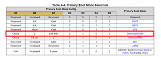
  2. Switch the boot mode to UART primary and Ethernet backup mode.
  3. Connect an ethernet cable from the board’s Ethernet port to a PC port.
  4. Start monitoring the PC port connected to the board using Wireshark.
  5. Power on the board.

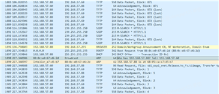
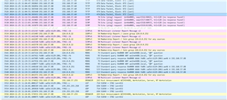
Customer got the Wireshark screenshot below.
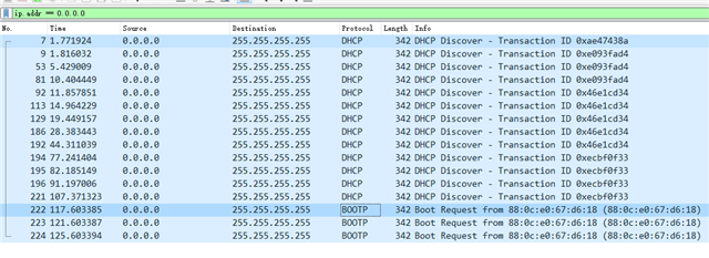
Customer is pretty sure the MAC address  88:0C:E0:67:D6:18 is for the AM2431 on their board, since the Ethernet port of the board is directly connected to their computers Ethernet port with a cable, and their computers MAC is totally different.

By the way, customer notices that for the backup boot, AM2431 only sends BOOTP request about 117s after power up. It is a little bit too long.  

If Ethernet Boot program/tools is ready, customer will change the Ethernet as Primary boot (with mode change switch) in next board spin. 

So please make sure the Ethernet boot tool we are working on can work for both Primary boot as well as backup boot.

Thanks,

Kevin

  • Hi Kevin,

    Thank you for the information.

    This looks good, ROM has initiated Ethernet boot as expected.

    I am working on the next steps of enabling a PC tool to send the required binaries, will update you once it is tested on my side.

    Regards,

    Nitika

  • Hi Kevin,

    Just to re-align on the requirement, below is the expected functionality:

    1. The device switches to Ethernet boot (ROM sends out BOOTP packets)

    2. ROM picks up the bootloader over Ethernet (via TFTP transfer).

    3. Next, the bootloader picks up the Application image over Ethernet, flashes it to the on-board QSPI NOR flash.

    Please correct me if I am wrong.

    Couple of questions on the above:

    1. Is the device expected to boot in Ethernet mode as well or to just use it as a flashing utility?

    2. After the flashing completes, does the customer switch back to OSPI boot mode or continue with Ethernet boot for all future power cycles of the board?

    Regards,

    Nitika

  • From above, we have tested 1 on the customer's board.

    We have verified 2 as well on our setup, we want to test it on the customer's board now so we are aligned on the progress.

    Please find the steps below for image transfer via TFTP with a Linux system (this is a one-time setup):

    1. Install DHCP server

    sudo apt install isc-dhcp-server

    • Disable services before configuration
      sudo systemctl disable --now isc-dhcp-server.service isc-dhcp-server6.service


    • DHCP server setup
      Run the ip link or ifconfig command to find the name of your network interface that will be connected to the board.
      eno1: flags=4163<UP,BROADCAST,RUNNING,MULTICAST>  mtu 1500
              inet 170.0.0.100  netmask 255.255.254.0  broadcast 170.0.0.255
              inet6 fefe::bbdd:3434:3d3d:5d5d  prefixlen 64  scopeid 0x20<link>
              ether aa:bb:cc:dd:ee:ff  txqueuelen 1000  (Ethernet)
              RX packets 2733979  bytes 1904440459 (1.9 GB)
              RX errors 0  dropped 3850  overruns 0  frame 0
              TX packets 796807  bytes 84534764 (84.5 MB)
              TX errors 0  dropped 0 overruns 0  carrier 0  collisions 0
       
      enxf8e43b8c: flags=4163<UP,BROADCAST,RUNNING,MULTICAST>  mtu 1500
              ether ff:ee:bb:88:ff:cc  txqueuelen 1000  (Ethernet)
              RX packets 95  bytes 31160 (31.1 KB)
              RX errors 0  dropped 0  overruns 0  frame 0
              TX packets 89  bytes 17445 (17.4 KB)
              TX errors 0  dropped 0 overruns 0  carrier 0  collisions 0
       
      lo: flags=73<UP,LOOPBACK,RUNNING>  mtu 65536
              inet 127.0.0.1  netmask 255.0.0.0
              inet6 ::1  prefixlen 128  scopeid 0x10<host>
              loop  txqueuelen 1000  (Local Loopback)
              RX packets 85238  bytes 7244462 (7.2 MB)
              RX errors 0  dropped 0  overruns 0  frame 0
              TX packets 85238  bytes 7244462 (7.2 MB)
              TX errors 0  dropped 0 overruns 0  carrier 0  collisions 0

      On my setup, a USB to Ethernet adapter is connected to one end on the PC and other to board.
      *enxf8e43b8c is the interface for usb-to-ethernet adapter.

    • Do following changes in /etc/dhcp/dhcpd.conf
      subnet 192.168.0.0 netmask 255.255.254.0
      {
      range dynamic-bootp 192.168.0.2 192.168.0.5;
      if substring (option vendor-class-identifier, 0, 16) = "TI K3 Bootp Boot"
      {
      filename "sbl_null.release.hs_fs.tiimage";
      }
      default-lease-time 60000;
      max-lease-time 720000;
      next-server 192.168.0.1;
      }


    • Do following changes in /etc/default/isc-dhcp-server
      DHCPDv4_CONF=/etc/dhcp/dhcpd.conf
      INTERFACESv4="enxf8e43b8cffe8"
      INTERFACESv6=""


    • For your interface, change IP address and netmask to next-server and your netmask
      sudo ifconfig enxf8e43b8cffe8 192.168.0.1 netmask 255.255.254.0


    • Enable DHCP
      sudo systemctl enable --now isc-dhcp-server
    • To see if there is any configuration error or if DHCP is running, run the below command. 
      If its shows error then something is wrong with configuration

      sudo service isc-dhcp-server status

    2. Setup tftp using this link - linuxhint.com/.../

    • Suppose your tftp directory is /tftp. You need to put <mcu_plus_sdk>/tools/boot/sbl_prebuilt/am243x-evm/sbl_null.release.hs_fs.tiimage  in the /tftp folder.

    3. Change boot modes to Ethernet boot and switch on the board.

    • SBL will be loaded automatically over Ethernet, indicated by (last) transfer.


    To verify the image transfer:

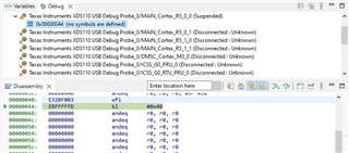
    1. Connect to R5F0_0 core, you will see that it is halted at wfi instruction (in Disassembly tab)

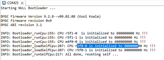
    2. Or, if you connect to the UART terminal and power-cycle the board. Once SBL is loaded, the below logs can be seen on the terminal.


    Do let me know if you face any issues with the configuration.

    Regards,

    Nitika

  • Hi Nitika,

    Regarding your questions:

    1.   We just use the Ethernet and the tools you are developing as a flashing utility, i.e. debricking/unbricking..

    2.  Once the flashing completes,  the board will switch back to OSPI mode.  

    Regards,

    Larry

  • Hi Nitika,

    Thanks a lot for your support.

    Sorry for missing communicate this. Our development enviroment is Windows.   May we get the tool running in Windows?   

    thanks a lot.

    Larry

  • Hi Larry,

    Thank you for the information.

    Allow me some time to get back to you on the Windows requirement.

    Regards,

    Nitika

  • Hi Larry,

    For implementing the above steps you will need a TFTP and DHCP server setup in the Windows system, same as the one given above.

    Update on the Ethernet SBL development: We are working on the new ENET based SBL and a python based PC tool for the flashing requirement, we are currently debugging a packet drop issue which is a blocker for the end of this week delivery. We will post updates on this thread as we make progress.

    Please note: The SBL has been developed with AM64x-SK EVM (with DP83867 ETHPHY, RGMII interface and OSPI as the flash media). This will have to be further modified as per your custom board.

    Regards,

    Nitika

  • Hi Larry, Kevin,

    We were able to resolve the packet drop issue and have been able to test Ethernet boot successfully on our end with the above mentioned device configuration.

    I will share the project along with the Ethernet boot guide by tomorrow.

    Regards,

    Nitika

  • Hi Nitika,

    Thanks for the good news, appreciate it!

    Kevin

  • Hi Larry, Kevin,

    Please find the project in the zip file below. The ReadMe file present in it gives information about the files and how to add them to a MCU+ SDK installer.

    Ethernet_boot.zip

    Please note: The project has been created on MCU+ SDK 10.0 baseline - https://www.ti.com/tool/download/MCU-PLUS-SDK-AM64X/10.00.00.20

    Ethernet Boot documentation: Ethernet Boot Guide-v1-20241108.pdf

    Regards,

    Nitika

  • Hi Nitika,

    Thanks a lot for the tools.  We are testing it.  Tftpd64 is used as the DHCP server and TFTP server since our dev environment is Windows. 

    We notice the DHCP server receives the BOOTP request from our board but the board's IP address is not assigned as expected.  

    Could you pls help test whether Tftpd64 is compatible with the tool and update the guide with it?  

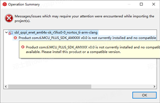
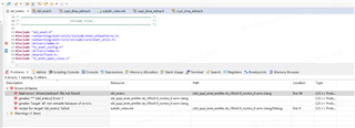
    When we compile the project you posted, CCS prompts two errors as below.  Could you pls help package the correct files and post the project again? Thanks a lot in advance.

    1.   

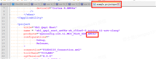
    It seems there is one typo in the configuration file(AMxxx --> AM64x):


    2.  edma.h is missing.

    Best regards,

    Larry

  • Hi Larry,

    Which SDK version are you working with?

    Regards,

    Nitika

  • Hi Nitika,

    We are using AM64x MCU Plus SDK 10.0.0.20.  

    Regarding Error 1,  if we change the text string from AMxxx to AM64x as below,  the error will be gone.  We'd like to know whether this change is correct. 

    Best regards,

    Larry

  • Hi Larry,

    Yes that change is correct, the example I shared was created from an internal repo so there was version mismatch.

    Please find the modified project below for AM64x MCU+ SDK 10.0.0.20

    4505.Ethernet_boot.zip

    Regards,

    Nitika

  • Hi Nitika,

    Thanks a lot for the updated project. It can be compiled successfully now.

    Since our dev environment is Windows 10,  we use Tftpd64, a widely-used open source DHCP and TFTP server for Windows.     It can be downloaded from  Github:  https://pjo2.github.io/tftpd64/

    Could you pls help verify/test whether the Python tools you provided can work smoothly with Tftpd64 ?  

    We are not familiar with the Python tool and it will be very difficult for us  to run the test.   Thanks a lot.

    Larry

  • Hi Larry,

    Let me look into this and get back to you in some time.

    Regards,

    Nitika

  • Hi Nitika,

    Tftpd64 is not necessarily the software which have to be used. 

    What we need is a verified software bundle of your tool and whatever DHCP server&TFTP server software,  which can work together smoothly in Windows 10. 

    Hope this helps.  Thanks a lot.

    Regards,

    Larry

  • Hi Nitika,

    Thanks for your support. As you know that the background of using Ethernet boot is for the "debricking situation", so in this situation, it mostly happens at the production line, the people in the production line only have access to Windows not Linux. Hence, it is very important for customer to have a verified software that could be used in Windows 10.

    Customer hopes to get this solution by the end of Nov. Could you please help on that?

    Many Thanks,

    Kevin

  • Hi Kevin, Larry,

    Some background on the Ethernet boot implementation, there are mainly 2 steps in this process:

    1. ROM bootloader: TFTP and DHCP server should be running on the PC to respond to the ROM (assign an IP and send the SBL to the board).
    2. Secondary bootloader (sbl_ospi_enet): The received SBL and python based tool establish the network between the PC and board, transfer the appimage and flash it.
    We are not familiar with the Python tool and it will be very difficult for us  to run the test. 

    The choice of a TFTP and a DHCP server does not depend on the TI software.

    Any TFTP and DHCP server should be running on the host machine, it just needs to be configured with same parameters (IP address, IP range, etc) as given in the Ethernet boot guide for Linux.

    Once the board reaches Step 2 above, the TFTP and DHCP server are no longer used.

    we use Tftpd64, a widely-used open source DHCP and TFTP server for Windows. 

    Tftpd64 is a suitable choice. Can you let me know what issues you were facing with this?

    Regards,

    Nitika

  • Hi Nitika,

    We set up the Tftpd64 and power up the board with Ethernet boot mode.  The wireshark shows a IP address is assigned to the board.  Then we run the Python tool but it responds a IP address binding error.  And the board still sends BOOTP request.

    It looks to me the tool and the image is not verified in Windows system yet. We don't have the knowledge to make the tool run in Windows if it is not verified yet.

    Like, I see the Python tool use the Socket library.  I'm not sure whether the tool rely on some system service to run.  I don't know whether Windows provides such services.  And I don't know how should the Tftpd64 be configured to provide service to meet the tool's requirement, or the tool should be tweaked to run on Windows system.

    Our project schedule is very tight and we can't afford to debug the tool in the platform on which it is not verifed yet.  We need the tool is verified in Windows system first, then we'll test it.  

    Thanks & regards,

    Larry

  • Hi Larry,

    Apologies if my explanation was not clear, let me elaborate on my above reply. Firstly, the python script does not work with Tftpd64.

    When the board is powered on,

    Step 1: Board sends BOOTP requests and your DHCP server responds to it and assigns an IP.

    Step 2: Board sends TFTP read request and your TFTP server send the sbl_opsi_enet image to the board.

    Beyond this point, the software no longer uses the TFTP and DHCP server.

    Step 3: SBL starts execution, assigns a static IP to the board, does port linkup and sends out linkup complete packet.

    Step 4: The python script already has the board static IP hard-coded as source IP receives the linkup packet and starts appimage transfer.


    The reason why you are still seeing BOOTP packets could be because Tftpd64 is not configured properly causing the SBL transfer to fail.

    Can you please share the wireshark logs with me so I can pinpoint the issue?

    Regards,

    Nitika

  • Additionally, please note that we have tested the python script with Windows (step 3 and step 4) as well. The steps for the same are present on Page 4 of the Ethernet boot guide.

    From our testing, there are only 2 requirements from a Windows system to run the python script:

    1. There should be no firewall blocking python from sending and receiving packets over the Host ethernet port

    2. You should have admin rights to run powershell and add a static ARP entry (steps on page 4 of the guide)

    Regards,

    Nitika

  • Hi Nitika,

    Thanks for your feedback!

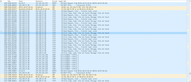
    Per your request, please see the Wireshark log captured during customer's test with the Ethernet Boot tool shown below.

    EthernetBoot.pcapng

    Please let us know if you find any clue based on the log, many thanks!

    Kevin

  • Hi Nikita,

    As the Wireshark log Kevin posted above,  

    MAC 88:0c:e0:67:d6:2d is that of the board with AM2431.

    192.168.57.90 is the IP of PC running the boot tool and Tftpd64(and Wireshark).

    192.168.57.60 is the IP assigned to the AM2431 board.

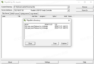
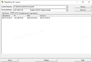
    The screenshots of Tftpd64 are:

    We saw you provided two projects with OSPI and QSPI respectively.  We put both images on the Tftp directory.  On our board, we use QSPI chip GD25Q64ESIG.

    Regards,

    Larry

  • Hi,

    As per the wireshark logs, the board is getting an IP from the DHCP server as expected but the TFTP transfer is failing with error code: File not found. This usually happens when the file is not present in the TFTP root directory or the filename is incorrect.

    The directory looks correct. Can you confirm that you have added sbl_ospi_enet.Release.hs_fs.tiimage in the DHCP server's Boot File option? Please share your DHCP settings as well.

    Regards,

    Nitika

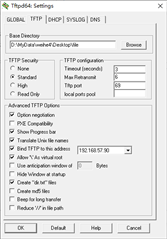
  • Hi Nikita,

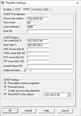
    Here is the screenshot of DHCP server setting:

    We didn't find the Boot File option for DHCP.   Click the button "Show Dir" shows the same file list as in last post.

    Regards,

    Larry

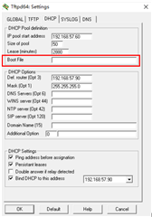
  • In your setup, the Boot File option is here

    Please add the file name (sbl_ospi_enet.Release.hs_fs.tiimage) here and try again.

    Regards,

    Nitika

  • Hi Nitika,

    We add the file name in th Boot File option and run the test again.   The board starts getting the image via TFTP.

    But the Wireshark log shows the TFTP transfer stuck at the last packet.  After several times of re-transfer, the board start sending BOOTP again.

    192.168.57.60 is the board.  192.168.57.88 is the PC running Tftpd64.

    And at some time, the board prints the message via UART as below:

    Could you pls provide any comments/advices ? 

    Thanks & regards,

    Larry

  • Hi Larry,

    Just to confirm, you are running this on which board, AM64x-SK or your custom board?

    The multiple prints seen for the last TFTP packet is expected. The fact that you are seeing logs on UART terminal means the SBL transfer was successful and the board has started executing the SBL.

    From the UART logs, it looks like PHY enable is failing. Can you tell me what PHYs you have on-board?

    Regards,

    Nitika

  • Hi Nikita,

    We are running on our custom board.  The MCU is AM2431BSDGHIALVR, Ethernet PHY is DP83826,  and the flash is  a QSPI chip GD25Q64ESIG from GigaDevice. 

    One thing to add,  we see the whole process(BOOTP+TFTP) typically repeat two times: first time the TFTP server sends the last packet  several times (no ACK from the board),  then the board start over from BOOTP.  Again the TFTP server sends the last packet only two times(no ACK received).  Then after a long time(tens of minutes ), the board print the message via UART.  

    Do you mean it is as expected that the board doesn't send ACK to the last packet ?    

    Best regards,

    Larry

  • Hi larry,

    There is a warm reset workaround implemented in every SBL that reboots the board after the SBL is received to prevent CPSW register lockup.

    I believe in your use case that is not necessary since it is not a production system. You can go ahead and comment out that section of code in your example.

    In main.c file, you can remove the below code section

    #ifndef DISABLE_WARM_REST_WA
       /* Warm Reset Workaround to prevent CPSW register lockup */
       if (!Bootloader_socIsMCUResetIsoEnabled())
       {
           Bootloader_socResetWorkaround();
       }
    #endif

    Rebuild the example in Release mode and replace the .tiimage file in your tftp folder with the new generated file.

    We have not seen tens of minutes of delay during our testing in running the SBL, can you please make the above change and let me know if you still see the delay?

    Regards,

    Nitika

  • Hi Nitika,

    The long delay turns out to be due to the wrong flash configuration. With correct flash configuration the delay disappears(the last packet still got No ACK.). 

    But both the board and the Python tool stuck at Linkup.  And the board don't respond to Ping(see the Wireshark log).  The Windows firewall has been disabled.

    Here are the screenshots:

    Any comments on the direction we can look into?  

    Thanks & regards,

    Larry

  • Hi Larry,

    From the UART logs it looks like port linkup is not happening on the board, the python script fails for the same reason as linkup acknowledgement packet is not being send out from the board.

    Can you make sure that the ethernet cable is connected properly?

    Additionally, the PHY on your board is different from the one on AM64x-sk board. As stated earlier, you will have to modify that as well.

    Regards,

    Nitika

  • Hi Nitika,

    The Ethernet cable is well connected. 

    In our board, the DP83826 has been configured with hardware bootstrap as:

    enhanced mode,

    auto-negotiaion enabled, Odd Nibble Detection enabled, 

    PHY address=0x07,

    RMII master mode,  LED1 on Pin31,

    RMII_CRS_DV, Signal Energy Detection enabled,

    Auto MDIX enabled, MDIX disabled.

    We made the following changes per the PHY DP83826 on our board:

    1. In Sysconfig, change the MAC address list; assign the MDIO and other pins accordingly.

    2. In Sysconfig,  disable MAC Port 1, Enable MAC Port 2, since DP83826 is connected to RMII2 of AM2431.

    3. In sbl_enet.h, change the HOST MAC address, source IP(192.168.57.61, the board's IP ), destination IP(192.168.57.88, the PC's IP ) accordingly.

    4. In sbl_enet.c, change the macMode to RMII.

    Could you pls comments what else we can modify to adapt to the PHY and the board?

    By the way, it seems the SDK docs and example projects are all based on the ETHPHY module(in SysConfig). 

    In your project, the ETHPHY module in SysConfig is not added.

    I'm not sure whether it will ease the work of PHY adaption if ETHPHY module is used since the SDK docs and examples can be referenced.

    I wonder what code in your project can be commented out if ETHPHY module is added and configured.   

    Thanks & regards,

    Larry

  • Hi Larry,

    The ETHPHY module is a recent addition made to ease the process of PHY integration.

    I can help you with the new configuration. Allow me some time to modify the project with the information you have provided above.

    Regards,

    Nitika

  • Hi Larry,

    Are you using your own PHY driver for DP83826 or a one provided by TI? Can you please share the PHY driver you are using?

    Regards,

    Nitika

  • Hi Nitika,

    We just modied the project your provided.   What we changed are listed in my last post.   

    Pls notice the DP83826 configuration is implemented with hardware bootstrap.   I guess we don't need to configure these in FW again.

    Best regards,

    Larry

  • Hi Larry,

    Pls notice the DP83826 configuration is implemented with hardware bootstrap.   I guess we don't need to configure these in FW again.

    That is correct, no configuration will be needed in the application again but the application needs to bind a PHY driver to the PHY device, this driver implements the PHY state machine required to handle the lifecycle of the PHY - from initialization to link establishment.

    You can see in the board.c file, we use DP83867 driver (PHY present on AM64x-SK). I wanted to know, do you have your own custom driver for DP83826 used on your board?

    Regards,

    Nitika

  • Hi Nitika,

    We don't have custom PHY driver for DP83826 yet.  That's why we want to use ETHPHY module to ease the work.   

    The question is if we add ETHPHY module into the your project, which files/code shall be modified/deleted (since your project already has PHY driver,  adding ETHPHY will create duplication and maybe collision)?

    Best regards,

    Larry

  • Hi Nitika,

    We also have one AM243-Lp board. Can this example be tested on this board? It uses DP83869, also not DP83867

    BR,

    Jianyu

  • Hi Jianyu,

    Are ethernet boot switches available on your AM243-lp board? If so, we can test on that as well.

    We will have to change the PHY used in board.c file for that.

    Regards,

    Nitika

  • Hi Nitika,

    I checked bootmode switch. It maps B3-B9 to switch 1-8. I set only B5, rest is 0.

    But the DHCP server doesn't assign any IP to the device. 

    So I searched online and found this, which is posted 2 years ago,

    https://e2e.ti.com/support/processors-group/processors/f/processors-forum/1189551/am2434-clarification-on-supported-boot-modes.

    Does this mean the LP-AM243 board, from https://www.ti.com/tool/LP-AM243, does not support Ethernet boot, too?

    Thanks,

    Jianyu

  • Hi Jianyu,

    Out-of-box we don't support Ethernet boot on AM64x and AM243x devices due to the errata i2331. I have not tested Ethernet boot with AM243x-LP in my setup.

    If you want to validate the drop on a device, you can do so on AM64x-SK board - https://www.ti.com/tool/SK-AM64B


    As discussed with Kevin, I have ported the Ethernet boot support on SDK version 10.1 with Ethphy and DP83826 support, I will share the same today.

    Please note: This will be an early drop package only for testing the feature on your board with DP83826 PHY, please make sure to move to the official SDK 10.1 once it is released on ti.com (planned for this month).

    Regards,

    Nitika

  • Hi Larry, Jianyu,

    I hope you have received the SDK 10.1 installer with the ethernet boot example, you will have to follow the readMe file attached with it for adding some minor changes in the PHY driver.

    Once you have done that, next step will be to modify the example according to your custom board requirements.

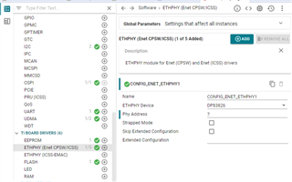
    For PHY related changes, you can go to the ETHPHY (Enet CPSW/ICSS) module in the example sysconfig and change the  'ETHPHY Device' to DP83826 and 'Phy Address' accordingly:

    Please let me know if you need any help.

    Regards,

    Nitika

  • Hi Nitika,

    Thanks for your support, customer feedback that the ethernet could be detected now using the 83826 PHY driver you provided.

    However, the example you provided is based on AM64x, customer wants to double confirm if they could apply this example directly on AM24?

    Thanks,

    Kevin

  • Hi Kevin, Larry,

    We did some testing at our end and the same AM64x based example works for AM243x-evm as well.

    Please note that the out-of-box AM243x TI EVM cannot support Ethernet boot due to board design limitations on RGMII 2 port (at the ROM bootloader level, the port is configured as ICSSG instead of CPSW). 

    Step 1: Board sends BOOTP requests and your DHCP server responds to it and assigns an IP.

    Step 2: Board sends TFTP read request and your TFTP server send the sbl_opsi_enet image to the board.

    Due to the hardware limitation, the above 2 steps (essentially the part where the ROM bootloader picks the SBL) cannot be done on AM243x-EVM. As a work-around for testing, we send the sbl_ospi_enet via UART and switch to OSPI boot mode to execute it.

    With this setup, we have sanity tested the SBL and the flashing utility works as expected.

    Since your custom board has no such hardware limitation and we have seen that the ROM bootloader part working correctly, you can follow the Ethernet boot guide and the same AM64x example should work directly.


    Kevin,

    We can have a call in case there are any more questions regarding the above.

    Regards,

    Nitika

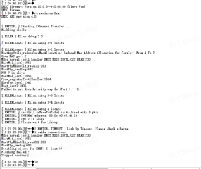
  • I have tested the demo on our board, the log of uart is as follows.

    ====================================================

    DMSC Firmware Version 10.0.8--v10.00.08 (Fiery Fox)
    DMSC Firmware revision 0xa
    DMSC ABI revision 4.0


    [ ENETSBL ] Starting Ethernet Transfer ...
    Enabling clocks!
    EnetAppUtils_reduceCoreMacAllocation: Reduced Mac Address Allocation for CoreId:1 From 4 To 2
    Open MAC port 2
    EnetPhy_bindDriver: PHY 7: OUI:080028 Model:13 Ver:01 <-> 'generic' : OK

    PHY 7 is alive
    EnetMod_ioctl: cpsw3G.macport1: Module is not open

    Cpsw_registerIoctlHandler: Failed to register IOCTL handler: -1, 1000502, 70031AF1

    EnetPer_ioctl: cpsw3g: Failed to do IOCTL cmd 0x01000110: -1

    Enet_ioctl: cpsw3g: IOCTL 0x01000110 failed: -1

    Failed to set dscp Priority map for Port 1 - -1
    [ ENETSBL ] initQs() txFreePktInfoQ initialized with 8 pkts
    [ ENETSBL ] EVM MAC address: 88:0c:e0:67:d6:2d

    [ ENETSBL ] PHY 7 is alive
    [ ENETSBL ] Please wait for Linkup ...

    [2024-12-11 05:42:54.578]
    RX:Cpsw_handleLinkUp: Port 2: Link up: 100-Mbps Full-Duplex

    =================================================================

    I debugged a little bit on demo enet_l2_multi_channel_am243x-evm on our board. It seems that module cspsw3G.macport1, address 0x7012d478 is not initialized.

    Since only port 2 is used, I am not sure why macport1 is used for initialization.

    Currently the board can detect network link. The python cannot linkup to the board.

    Yesterday I have faced this issue on demo enet_l2_multi_channel_am243x-evm but thought the reason might be SDK version issue.

    Jianyu

  • Hi Jianyu,

    The errors for Port 1 are due to dscp failure, the dev team is looking into that. Since these errors are only seen for Port 1, the functionality of Port 2 is not impacted, I have tested this.

    Additionally, there is a different issue I see from the logs-

    EnetPhy_bindDriver: PHY 7: OUI:080028 Model:13 Ver:01 <-> 'generic' : OK

    The EnetPhy_bindDriver is attaching the generic PHY driver to your on-board PHY instead of DP83826. 

    Can you share your generated ti_board_config.c file with me?

    Regards,

    Nitika

  • The file is attached

    8204.ti_board_config.c
    /*
     *  Copyright (C) 2021 Texas Instruments Incorporated
     *
     *  Redistribution and use in source and binary forms, with or without
     *  modification, are permitted provided that the following conditions
     *  are met:
     *
     *    Redistributions of source code must retain the above copyright
     *    notice, this list of conditions and the following disclaimer.
     *
     *    Redistributions in binary form must reproduce the above copyright
     *    notice, this list of conditions and the following disclaimer in the
     *    documentation and/or other materials provided with the
     *    distribution.
     *
     *    Neither the name of Texas Instruments Incorporated nor the names of
     *    its contributors may be used to endorse or promote products derived
     *    from this software without specific prior written permission.
     *
     *  THIS SOFTWARE IS PROVIDED BY THE COPYRIGHT HOLDERS AND CONTRIBUTORS
     *  "AS IS" AND ANY EXPRESS OR IMPLIED WARRANTIES, INCLUDING, BUT NOT
     *  LIMITED TO, THE IMPLIED WARRANTIES OF MERCHANTABILITY AND FITNESS FOR
     *  A PARTICULAR PURPOSE ARE DISCLAIMED. IN NO EVENT SHALL THE COPYRIGHT
     *  OWNER OR CONTRIBUTORS BE LIABLE FOR ANY DIRECT, INDIRECT, INCIDENTAL,
     *  SPECIAL, EXEMPLARY, OR CONSEQUENTIAL DAMAGES (INCLUDING, BUT NOT
     *  LIMITED TO, PROCUREMENT OF SUBSTITUTE GOODS OR SERVICES; LOSS OF USE,
     *  DATA, OR PROFITS; OR BUSINESS INTERRUPTION) HOWEVER CAUSED AND ON ANY
     *  THEORY OF LIABILITY, WHETHER IN CONTRACT, STRICT LIABILITY, OR TORT
     *  (INCLUDING NEGLIGENCE OR OTHERWISE) ARISING IN ANY WAY OUT OF THE USE
     *  OF THIS SOFTWARE, EVEN IF ADVISED OF THE POSSIBILITY OF SUCH DAMAGE.
     */
    /*
     * Auto generated file
     */
    #include "ti_board_config.h"
    
    /*
     * Auto generated file
     */


    /* ========================================================================== */
    /*                             Include Files                                  */
    /* ========================================================================== */
    
    #include <stdint.h>
    #include <enet.h>
    #include <dp83826.h>
    #include <enet_apputils.h>
    #include <kernel/dpl/SystemP.h>
    #include <kernel/dpl/AddrTranslateP.h>
    #include <networking/enet/core/src/phy/enetphy_priv.h>
    #include <networking/enet/core/src/phy/generic_phy.h>
    #include <drivers/gpio.h>
    #include <board/eeprom.h>
    #include "ti_board_open_close.h"
    #include "ti_drivers_open_close.h"
    #include "ti_drivers_config.h"
    
    
    #define ENET_GET_NUM_MAC_ADDR(num) ((num>>3)+1)
    #define ENET_MAC_ADDR_VALIDATE_MASK (0x01U)
    
    #define MSS_CPSW_CONTROL_PORT_MODE_RMII                                   (0x1U)
    #define MSS_CPSW_CONTROL_PORT_MODE_RGMII                                  (0x2U)
    
    #include <drivers/i2c.h>
    
    #define IO_EXPANDER_PORT0_OUTPUT_REG 	(0x04U)
    #define IO_EXPANDER_PORT0_DIR_REG 		(0x0CU)
    #define IO_EXPANDER_I2C_ADDR 			(0x22U)
    #define ENET_BOARD_NUM_MACADDR_MAX 		(4U)
    #define I2C_EEPROM_MAC_CTRL_OFFSET 		(0x40)
    #define I2C_EEPROM_MAC_DATA_OFFSET 		(0x42)
    
    static void EnetBoard_setMacPort2IOExpanderCfg(void);
    
    /* PHY drivers */
    extern Phy_DrvObj_t gEnetPhyDrvDp83826;
    extern Phy_DrvObj_t gEnetPhyDrvGeneric;
    
    /*! \brief All the registered PHY specific drivers. */
    static const EthPhyDrv_If gEnetPhyDrvs[] =
    {
        &gEnetPhyDrvDp83826,    /* DP83826 */
        &gEnetPhyDrvGeneric,    /* Generic PHY - must be last */
    };
    
    const EnetPhy_DrvInfoTbl gEnetPhyDrvTbl =
    {
        .numHandles = ENET_ARRAYSIZE(gEnetPhyDrvs),
        .hPhyDrvList = gEnetPhyDrvs,
    };
    
    
    /* ========================================================================== */
    /*                          Function Declarations                             */
    /* ========================================================================== */
    
    static const EnetBoard_PortCfg *EnetBoard_getPortCfg(const EnetBoard_EthPort *ethPort);
    
    static const EnetBoard_PortCfg *EnetBoard_findPortCfg(const EnetBoard_EthPort *ethPort,
                                                          const EnetBoard_PortCfg *ethPortCfgs,
                                                          uint32_t numEthPorts);
    
    static void EnetBoard_setEnetControl(Enet_Type enetType,
                                         Enet_MacPort macPort,
                                         EnetMacPort_Interface *mii);
    
    static void EnetBoard_enableExternalMux();
    
    /* ========================================================================== */
    /*                            Global Variables                                */
    /* ========================================================================== */
    /*!
     * \brief Common Processor Board (CPB) board's DP83826 PHY configuration.
     */
    static const Dp83826_Cfg gEnetCpbBoard_ConfigEnetEthphy0PhyCfg =
    {
    };
    /*
     * am64x-evm board configuration.
     *
     * RMII/RGMII PHY connected to am64x-evm CPSW_3G MAC port.
     */
    static const EnetBoard_PortCfg gEnetCpbBoard_am64x_evm_EthPort[] =
    {
        {    /* "CPSW3G" */
            .enetType = ENET_CPSW_3G,
            .instId   = 0U,
            .macPort  = ENET_MAC_PORT_2,
            .mii      = {ENET_MAC_LAYER_MII, ENET_MAC_SUBLAYER_REDUCED},
            .phyCfg   =
            {
                .phyAddr         = 7,
                .isStrapped      = false,
                .skipExtendedCfg = true,
    			.extendedCfg     = &gEnetCpbBoard_ConfigEnetEthphy0PhyCfg,
    			.extendedCfgSize = sizeof(gEnetCpbBoard_ConfigEnetEthphy0PhyCfg)
            },
            .flags    = 0U,
        },
    };
    
    /* ========================================================================== */
    /*                          Function Definitions                              */
    /* ========================================================================== */
    
    const EnetBoard_PhyCfg *EnetBoard_getPhyCfg(const EnetBoard_EthPort *ethPort)
    {
        const EnetBoard_PortCfg *portCfg;
    
        portCfg = EnetBoard_getPortCfg(ethPort);
    
        return (portCfg != NULL) ? &portCfg->phyCfg : NULL;
    }
    
    static void EnetBoard_enableExternalMux()
    {
        /* Enable external MUXes, if any, as per the board design */
    }
    
    static const EnetBoard_PortCfg *EnetBoard_getPortCfg(const EnetBoard_EthPort *ethPort)
    {
        const EnetBoard_PortCfg *portCfg = NULL;
    
        if (ENET_NOT_ZERO(ethPort->boardId & ENETBOARD_CPB_ID) || 
            ((portCfg == NULL) && ENET_NOT_ZERO(ethPort->boardId & ENETBOARD_LOOPBACK_ID)))
        {
            portCfg = EnetBoard_findPortCfg(ethPort,
                                            gEnetCpbBoard_am64x_evm_EthPort,
                                            ENETPHY_ARRAYSIZE(gEnetCpbBoard_am64x_evm_EthPort));
        }
        return portCfg;
    }
    
    static const EnetBoard_PortCfg *EnetBoard_findPortCfg(const EnetBoard_EthPort *ethPort,
                                                          const EnetBoard_PortCfg *ethPortCfgs,
                                                          uint32_t numEthPorts)
    {
        const EnetBoard_PortCfg *ethPortCfg = NULL;
        bool found = false;
        uint32_t i;
    
        for (i = 0U; i < numEthPorts; i++)
        {
            ethPortCfg = &ethPortCfgs[i];
    
            if ((ethPortCfg->enetType == ethPort->enetType) &&
                (ethPortCfg->instId == ethPort->instId) &&
                (ethPortCfg->macPort == ethPort->macPort) &&
                (ethPortCfg->mii.layerType == ethPort->mii.layerType) &&
                (ethPortCfg->mii.sublayerType == ethPort->mii.sublayerType))
            {
                found = true;
                break;
            }
        }
    
        return found ? ethPortCfg : NULL;
    }
    
    void EnetBoard_getMiiConfig(EnetMacPort_Interface *mii)
    {
        mii->layerType      = ENET_MAC_LAYER_MII;
        mii->variantType  = ENET_MAC_VARIANT_NONE;
        mii->sublayerType   = ENET_MAC_SUBLAYER_REDUCED;
    }
    
    int32_t EnetBoard_setupPorts(EnetBoard_EthPort *ethPorts,
                                 uint32_t numEthPorts)
    {
        CSL_main_ctrl_mmr_cfg0Regs *regs = (CSL_main_ctrl_mmr_cfg0Regs *)(uintptr_t)CSL_CTRL_MMR0_CFG0_BASE;
        EnetAppUtils_MmrLockState prevLockState;
    
        DebugP_assert(numEthPorts == 1);
        DebugP_assert(ethPorts->mii.sublayerType == ENET_MAC_SUBLAYER_REDUCED);
    
        EnetBoard_enableExternalMux();
        /* Override the ENET control set by board lib */
        EnetBoard_setEnetControl(ethPorts->enetType, ethPorts->macPort, &ethPorts->mii);
    
        prevLockState = EnetAppUtils_mainMmrCtrl(ENETAPPUTILS_MMR_LOCK1, ENETAPPUTILS_UNLOCK_MMR);
    
        switch(ethPorts->macPort)
        {
            case ENET_MAC_PORT_1:
                CSL_FINS (regs->ENET1_CTRL, MAIN_CTRL_MMR_CFG0_ENET1_CTRL_PORT_MODE_SEL, MSS_CPSW_CONTROL_PORT_MODE_RMII);
                break;
            case ENET_MAC_PORT_2:
                CSL_FINS (regs->ENET2_CTRL, MAIN_CTRL_MMR_CFG0_ENET2_CTRL_PORT_MODE_SEL, MSS_CPSW_CONTROL_PORT_MODE_RMII);
                EnetBoard_setMacPort2IOExpanderCfg();
                break;
            default:
                DebugP_assert(false);
        }
    
        if (prevLockState == ENETAPPUTILS_LOCK_MMR)
        {
            EnetAppUtils_mainMmrCtrl(ENETAPPUTILS_MMR_LOCK1, ENETAPPUTILS_LOCK_MMR);
        }
    
        /* Nothing else to do */
        return ENET_SOK;
    }
    
    static void EnetBoard_setEnetControl(Enet_Type enetType,
                                         Enet_MacPort macPort,
                                         EnetMacPort_Interface *mii)
    {
    
    }
    
    void EnetBoard_getMacAddrList(uint8_t macAddr[][ENET_MAC_ADDR_LEN],
                                  uint32_t maxMacEntries,
                                  uint32_t *pAvailMacEntries)
    {
        int32_t status = ENET_SOK;
        uint32_t macAddrCnt;
        uint32_t i;
        uint8_t macAddrBuf[ENET_BOARD_NUM_MACADDR_MAX * ENET_MAC_ADDR_LEN];
        uint8_t numMacMax;
        uint8_t validNumMac = 0;
    
        status = EEPROM_read(gEepromHandle[CONFIG_EEPROM0],  I2C_EEPROM_MAC_CTRL_OFFSET, &numMacMax, sizeof(uint8_t));
        EnetAppUtils_assert(status == ENET_SOK);
        EnetAppUtils_assert(ENET_GET_NUM_MAC_ADDR(numMacMax) <= ENET_BOARD_NUM_MACADDR_MAX);
        macAddrCnt = EnetUtils_min(ENET_GET_NUM_MAC_ADDR(numMacMax), maxMacEntries);
    
        EnetAppUtils_assert(pAvailMacEntries != NULL);
    
        status = EEPROM_read(gEepromHandle[CONFIG_EEPROM0], I2C_EEPROM_MAC_DATA_OFFSET, macAddrBuf, (macAddrCnt * ENET_MAC_ADDR_LEN));
        EnetAppUtils_assert(status == ENET_SOK);
    
        /* Save only those required to meet the max number of MAC entries */
        /* Validating that the MAC addresses from the EEPROM are not MULTICAST addresses */
        for (i = 0U; i < macAddrCnt; i++)
        {
            if(!(macAddrBuf[i * ENET_MAC_ADDR_LEN] & ENET_MAC_ADDR_VALIDATE_MASK)){
                memcpy(macAddr[validNumMac], &macAddrBuf[i * ENET_MAC_ADDR_LEN], ENET_MAC_ADDR_LEN);
                validNumMac++;
            }
        }
    
        *pAvailMacEntries = validNumMac;
    
        if (macAddrCnt == 0U)
        {
            EnetAppUtils_print("EnetBoard_getMacAddrList Failed - IDK not present\n");
            EnetAppUtils_assert(false);
        }
    }
    
    static void EnetBoard_setMacPort2IOExpanderCfg(void)
    {
        I2C_Transaction i2cTransaction;
        uint8_t buffer[2];
    
        I2C_Transaction_init(&i2cTransaction);
        i2cTransaction.writeBuf     = buffer;
        i2cTransaction.writeCount   = 2U;
        i2cTransaction.targetAddress = IO_EXPANDER_I2C_ADDR;
    
        /* Configure MDIO sel pin */
        /* Set output to high */
        buffer[0] = IO_EXPANDER_PORT0_OUTPUT_REG + 1; /* Port 1 */
        buffer[1] = (0x01 << 4); /* Pin 4 */
        I2C_transfer(I2C_getHandle(CONFIG_I2C1), &i2cTransaction);
    
        /* set pin to output */
        buffer[0] = IO_EXPANDER_PORT0_DIR_REG + 1;
        buffer[1] = ~(0x1 << 4);
        I2C_transfer(I2C_getHandle(CONFIG_I2C1), &i2cTransaction);
    
    }
    
    /*
     * Get ethernet board id
     */
    uint32_t EnetBoard_getId(void)
    {
        return ENETBOARD_AM64X_AM243X_EVM;
    }


    void Board_init(void)
    {
    
    }
    
    void Board_deinit(void)
    {
    
    
    }
    

    Due to the hardware limitation, the above 2 steps (essentially the part where the ROM bootloader picks the SBL) cannot be done on AM243x-EVM. As a work-around for testing, we send the sbl_ospi_enet via UART and switch to OSPI boot mode to execute it.

    I'll try this on LP-AM243x today.

  • I have rebuilt the SDK, now the phy can correctly bind to 83826. Here is the UART output.

    DMSC Firmware Version 10.0.8--v10.00.08 (Fiery Fox)
    DMSC Firmware revision 0xa
    DMSC ABI revision 4.0
    
    
    [ ENETSBL ] Starting Ethernet Transfer ...
    Enabling clocks!
    EnetAppUtils_reduceCoreMacAllocation: Reduced Mac Address Allocation for CoreId:1 From 4 To 2 
    Open MAC port 2
    EnetPhy_bindDriver: PHY 7: OUI:080028 Model:13 Ver:01 <-> 'DP83826' : OK
    
    PHY 7 is alive
    EnetMod_ioctl: cpsw3G.macport1: Module is not open
    
    Cpsw_registerIoctlHandler: Failed to register IOCTL handler: -1, 1000502, 70031001
    
    EnetPer_ioctl: cpsw3g: Failed to do IOCTL cmd 0x01000110: -1
    
    Enet_ioctl: cpsw3g: IOCTL 0x01000110 failed: -1
    
    Failed to set dscp Priority map for Port 1 - -1 
    [ ENETSBL ] initQs() txFreePktInfoQ initialized with 8 pkts
    [ ENETSBL ] EVM MAC address: 88:0c:e0:67:d6:2d
    
    [ ENETSBL ] PHY 7 is alive
    [ ENETSBL ] Please wait for Linkup ...
    
    [2024-12-12 11:09:22.395]
    RX:Cpsw_handleLinkUp: Port 2: Link up: 100-Mbps Full-Duplex

    Then I start the python script, the output is,

    D:\CD3E-AP\Ethernet\Ethernet_boot>python enet_uniflash.py --cfg=default_sbl_enet_app.cfg
    [LOG] Parsing config file ...
    [LOG] Ensure that sbl_qspi_enet has already been sent over before running this script.
    [LOG] Found 1 command(s) !!!
    [LOG] Creating socket
    Starting Linkup ...
    Starting Linkup ...
    Starting Linkup ...
    Starting Linkup ...
    Starting Linkup ...
    [ERROR] Connection timed out too many times for link-up. Check connection to EVM.
            Power cycle EVM and run this script again !!!