This thread has been locked.

If you have a related question, please click the "Ask a related question" button in the top right corner. The newly created question will be automatically linked to this question.

LP-AM243: Supplying 5V without USB C?

Other Parts Discussed in Thread: TPS22965

Tool/software:

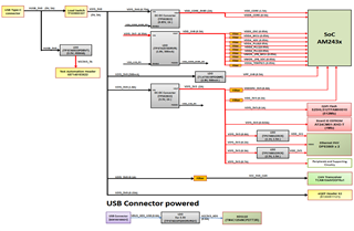
I've designed a custom booster pack to leverage the AM243X-LP for an industrial application. I've been powering the LP with a 5V PSU directly which for several years seems to work fine. The documentation goes into a lot of effort to describe the USB C power architecture, but never explicitly defines that it's the only way to power the board - is there any risk with powering via an external 5V supply in this way?

If it's not safe, what's the best way to avoid using a USB-C PSU to provide power?

I have other peripherals that also need a larger 5V supply than the LP can supply, so I'd rather use one 5V supply to power both the LP and the peripherals.


Thanks!

  • Hello Tron, 

    Thank you for the query.

    I am not sure on the changes you have done to make the LP-243 work without USB power.

    Please refer to the AM64x EVM in case you are looking to power the board from a stand-alone supply.

    The power architecture is application dependent.

    Regards,

    Sreenivasa

  • Hi Sreenivasa,

    I've made no changes. The LP will function seemingly perfectly if you connect a 5V supply to the 5V rail. Because of this, we provide the 5V supply to our shield, which in turn energises the LP.

    What I'm wondering is if there is a risk in bypassing the USB C that we also need to handle.

  • Hello Tron, 

    Thank you.

    is the query for the LP or for custom implementation.

    Regards,

    Sreenivasa

  • It's for the LP

  • Hello Tron, 

    Thank you.

    Are you connecting the supply to TP53

    I assume you are connecting a regulated and current controlled source.

    Regards,

    Sreenivasa

  • Hello Tron, 

    Thank you.

    I check internally and i understand the team has checked LP with rasberrypi supply 5V 3A.

    This is a Type C connector.

    Regards,

    Sreenivasa

  • Sreenivasa, this doesn't answer my question. I don't want to use the USB C connector.

  • No, not TP53. We've been connecting a 5V supply to VSYS_5V0 via the boosterpack headers. This is because we have peripherals on the boosterpack that require more current than the LP can provide. This allows us to power both the LP without an additional USB C power supply and the peripherals.

    Is this ok to do? The documentation spends a lot of time talking about the USB C connector, but we don't want to use that.

  • Hello Tron, 

    Thank you.

    Based on the inputs from the team, this is not something we have tested on the LP. The recommendation is to follow the below section 

    3 Board Setup 3.1 Power Requirements

    https://www.ti.com/lit/ug/spruj12f/spruj12f.pdf

    Regards,

    Sreenivasa

  • I've read all of that. I don't want to use the USB C connector because it requires a separate USB C power supply and that's wasteful and redundant. Hence why I'm requesting advice on how to bypass it safely.

    Perhaps there's someone else at TI who has more experience with the schematics so we can stop talking in circles?

  • Hello Tron, 

    Thank you.

    Nothing that i am aware that i can suggest.

    I can check with the team internally next week (due to US holidays) and update you.

    Regards,

    Sreenivasa

  • Thanks, Sreenivasa.

    For extra context, this is how we're supplying 5V via the custom boosterpack: with a TPS27081 on our custom boosterpack.

    The 5V rail as labelled above connects directly to VSYS_5V0 of the LP, so while LD9 illuminates as if there's a power error, the LP does appear to work fine. We're essentially bypassing the onboard TPS22965 which takes 5V from the USB C connector. This allows us to both supply power without needing a separate USB C transformer, without modifying the LP, and it allows us to remotely control whether the LP is powered on or off (or using a jumper to force it always on).

    I want to confirm whether the operation here is safe.

  • Hello Tron, 

    Thank you.

    We're essentially bypassing the onboard TPS22965

    Do you connect the supply to TP39 ?

    I suspect the load switch TPS22965 output will see a 5V supply. Can you please confirm. 

    I am not sure if this is a valid use case for the load switch.

    regards,

    Sreenivasa

  • Yes, as you can see in the LP schematics, the TPS22965 takes supply from the USB C and creates VSYS_5V0 (i.e. TP39) with it:

    So I assume it's ok to use my TPS27081 to supply 5V to the VSYS_5V0 net instead. It's worked fine for us and is preferential.

    I'm just looking for confirmation since there's a lot of talk in the docs pushing the USB C connector but no justification as to why USB C is used to supply power to the LP. Seems like a poor design choice to me.

  • Hello Tron, 

    Thank you.

    As i understand, the supply you are providing connects to the TPS22965 output.

    I am not sure if this is allowed use case for TPS22965. The device has QOD feature. Not sure if this is drawing continuous current. 

    Based on the data sheet seems this is not an expected use case.

    9.3.2 Quick Output Discharge (QOD)

    The TPS22965 includes a QOD feature. When the switch is disabled, a discharge resistor is connected between VOUT and GND. This resistor has a typical value of 225 Ω and prevents the output from floating while the switch is disabled.

    10.1.3 Output Capacitor (Optional)

    Becuase of the integrated body diode in the NMOS switch, a CIN greater than CL is highly recommended. A CL greater than CIN can cause VOUT to exceed VIN when the system supply is removed. This could result in current flow through the body diode from VOUT to VIN. A CIN to CL ratio of 10 to 1 is recommended for minimizing VIN dip caused by inrush currents during startup; however, a 10 to 1 ratio for capacitance is not required for proper functionality of the device. A ratio smaller than 10 to 1 (such as 1 to 1) could cause slightly more VIN dip upon turn-on due to inrush currents. This can be mitigated by increasing the capacitance on the CT pin for a longer rise time (see the Adjustable Rise Time section).

    You can start a new thread or i can reassign the thread for the load switch team to support.

    I will check with the team next week if we allow customer to connect supplies that have not been recommended to the LP. 

    Regards,

    Sreenivasa

  • The TPS22965 includes a QOD feature. When the switch is disabled, a discharge resistor is connected between VOUT and GND. This resistor has a typical value of 225 Ω and prevents the output from floating while the switch is disabled.

    This only means that the pull-down resistor will discharge 2.22mA when powered remotely, no? Nonetheless, I don't think this is a literal resistor, but an internal NMOS:

    My read from this is that if the TPS22965 has no supply at Vin then the NOT gate won't be energised and so the QOD NMOS won't be ON (i.e. the 'resistor' won't be 'connected' between Vout and GND), even with 5V at Vout from the TPS27081.

  • Hello Tron, 

    Thank you.

    As i understand this is not an allowed use case. Please refer below.

    10.1.3 Output Capacitor (Optional)

    Becuase of the integrated body diode in the NMOS switch, a CIN greater than CL is highly recommended. A CL greater than CIN can cause VOUT to exceed VIN when the system supply is removed. This could result in current flow through the body diode from VOUT to VIN. A CIN to CL ratio of 10 to 1 is recommended for minimizing VIN dip caused by inrush currents during startup; however, a 10 to 1 ratio for capacitance is not required for proper functionality of the device. A ratio smaller than 10 to 1 (such as 1 to 1) could cause slightly more VIN dip upon turn-on due to inrush currents. This can be mitigated by increasing the capacitance on the CT pin for a longer rise time (see the Adjustable Rise Time section).

    You can start a new thread or i can reassign the thread for the load switch team to support.

    Regards,

    Sreenivasa