Part Number: AM2431
Tool/software:
Hi,
I am testing phase delay base on example https://software-dl.ti.com/processor-industrial-sw/esd/motor_control_sdk/am243x/09_02_00_09/docs/api_guide_am243x/BASIC_SDFM_EXAMPLE_WITH_PHASE_DELAY.html
An issue is that our hardware design is different compared to the demo. GPI1 is not connected to SD chip and I need to modify it to GPI3.
Currently it would stuck in waiting for ack from PRU if phase compensation is enabled.
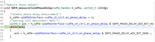
Based on the description of the sdfm_firmware_signle_axis_signle_pru, it seems is because GPO1 is not connected.
How do I modify the code so it can measure the delay in other GPIO?
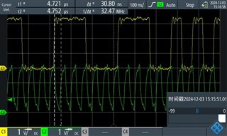
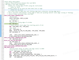
Another question is that, I measured the SD_data and SD_Clk (20Mhz).
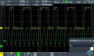
So the calculated result should be (50-20) = 30 ns?
Thanks,
Jianyu