Tool/software:
Hello,
On the TM4C123G, I aim to store data read from 6-channel ADCs by triggering the ADC using a timer interrupt and employing uDMA. However, with the configuration I've made, I can only see the values from the first channel in the target buffer of the uDMA.
I understand that the FIFO belonging to ADC 0 works on the principle of a "simple circular buffer," and I can see the start and end points of the retrieved data using the status register. However, do I need to perform any additional configuration in the uDMA-ADC setup to synchronize these start and end points? Or should the data in the FIFO be transferred to uDMA synchronously in burst mode?
I built my code based on the "adc_udma_pingpong" example code, and I’ve shared the significant parts below:
MAP_SysCtlPeripheralEnable(SYSCTL_PERIPH_ADC0);
MAP_SysCtlPeripheralEnable(SYSCTL_PERIPH_UDMA);
ROM_SysCtlPeripheralEnable(SYSCTL_PERIPH_TIMER0);
MAP_SysCtlPeripheralEnable(SYSCTL_PERIPH_TIMER1);
MAP_SysCtlPeripheralEnable(SYSCTL_PERIPH_GPIOE);
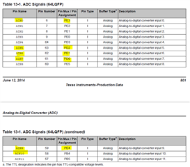
GPIOPinTypeADC(GPIO_PORTD_BASE, GPIO_PIN_0); //AIN7
GPIOPinTypeADC(GPIO_PORTD_BASE, GPIO_PIN_1); //AIN6
GPIOPinTypeADC(GPIO_PORTD_BASE, GPIO_PIN_2); //AIN5
GPIOPinTypeADC(GPIO_PORTB_BASE, GPIO_PIN_4); //AIN10
GPIOPinTypeADC(GPIO_PORTE_BASE, GPIO_PIN_4); //AIN9
GPIOPinTypeADC(GPIO_PORTE_BASE, GPIO_PIN_3); //AIN0
// ConfigureUART();
uDMAEnable();
IntEnable(UDMA_CHANNEL_ADC0);
uDMAControlBaseSet(pui8ControlTable);
ROM_IntEnable(INT_UDMA);
uDMAChannelAttributeDisable(UDMA_CHANNEL_ADC0,
UDMA_ATTR_ALTSELECT | UDMA_ATTR_HIGH_PRIORITY |
UDMA_ATTR_REQMASK);
uDMAChannelControlSet(UDMA_CHANNEL_ADC0 | UDMA_PRI_SELECT,
                      UDMA_SIZE_16 | UDMA_SRC_INC_NONE |
                      UDMA_DST_INC_16 | UDMA_ARB_1);

uDMAChannelControlSet(UDMA_CHANNEL_ADC0 | UDMA_ALT_SELECT,
                      UDMA_SIZE_16 | UDMA_SRC_INC_NONE |
                      UDMA_DST_INC_16 | UDMA_ARB_1);
uDMAChannelTransferSet(UDMA_CHANNEL_ADC0 | UDMA_PRI_SELECT,
UDMA_MODE_PINGPONG,
(void *)(ADC0_BASE + ADC_O_SSFIFO0),
&pui16ADCBuffer1, ADC_SAMPLE_BUF_SIZE);
uDMAChannelTransferSet(UDMA_CHANNEL_ADC0 | UDMA_ALT_SELECT,
UDMA_MODE_PINGPONG,
(void *)(ADC0_BASE + ADC_O_SSFIFO0),
&pui16ADCBuffer2, ADC_SAMPLE_BUF_SIZE);
uDMAChannelAttributeEnable(UDMA_CHANNEL_ADC0, UDMA_ATTR_USEBURST);
uDMAChannelEnable(UDMA_CHANNEL_ADC0);
ADCClockConfigSet(ADC0_BASE, ADC_CLOCK_SRC_PIOSC | ADC_CLOCK_RATE_HALF, 1);
SysCtlDelay(10);
IntDisable(INT_ADC0SS0);
ADCIntDisable(ADC0_BASE, 0);
ADCHardwareOversampleConfigure(ADC0_BASE, 4);
ADCSequenceDisable(ADC0_BASE, 0);
ADCSequenceConfigure(ADC0_BASE, 0, ADC_TRIGGER_TIMER, 0);
ADCSequenceStepConfigure(ADC0_BASE, 0, 0, ADC_CTL_CH7); //sira onemli
ADCSequenceStepConfigure(ADC0_BASE, 0, 1, ADC_CTL_CH6);
ADCSequenceStepConfigure(ADC0_BASE, 0, 2, ADC_CTL_CH5);//IE ve END sadece sonda
ADCSequenceStepConfigure(ADC0_BASE, 0, 3, ADC_CTL_CH10 );
ADCSequenceStepConfigure(ADC0_BASE, 0, 4, ADC_CTL_CH9);
ADCSequenceStepConfigure(ADC0_BASE, 0, 5, ADC_CTL_CH0 | ADC_CTL_IE | ADC_CTL_END);
ADCSequenceEnable(ADC0_BASE, 0);
ADCIntClear(ADC0_BASE, 0);
ADCSequenceDMAEnable(ADC0_BASE, 0);
ADCIntEnable(ADC0_BASE, 0);
IntEnable(INT_ADC0SS0);
ROM_TimerConfigure(TIMER0_BASE, TIMER_CFG_PERIODIC);
TimerConfigure(TIMER1_BASE, TIMER_CFG_SPLIT_PAIR |TIMER_CFG_B_PERIODIC);
ROM_TimerLoadSet(TIMER0_BASE, TIMER_A, ROM_SysCtlClockGet() / 100000); //10us
TimerLoadSet(TIMER1_BASE, TIMER_B, ROM_SysCtlClockGet() / 10000);
TimerControlTrigger(TIMER1_BASE, TIMER_B, true);
IntMasterEnable();
ROM_IntEnable(INT_TIMER0A);
ROM_TimerIntEnable(TIMER0_BASE, TIMER_TIMA_TIMEOUT);
ROM_TimerEnable(TIMER0_BASE, TIMER_A);
TimerEnable(TIMER1_BASE, TIMER_B);
(Detailed code snippets are included and can be added to the text above.)
I performed the initial configuration as mentioned above. I configured the ADC Sequence 0 interrupt as follows:
void ADCSeq0Handler(void)
{
ADCIntClear(ADC0_BASE, 0);
if ((uDMAChannelModeGet(UDMA_CHANNEL_ADC0 | UDMA_PRI_SELECT) == UDMA_MODE_STOP) &&
(pui32BufferStatus[0] == FILLING)) {
pui32BufferStatus[0] = FULL;
pui32BufferStatus[1] = FILLING;
}
else if ((uDMAChannelModeGet(UDMA_CHANNEL_ADC0 | UDMA_ALT_SELECT) == UDMA_MODE_STOP) &&
(pui32BufferStatus[1] == FILLING)) {
pui32BufferStatus[0] = FILLING;
pui32BufferStatus[1] = FULL;
}
if (pui32BufferStatus[0] == FULL) {
pui32BufferStatus[0] = EMPTY;
uDMAChannelTransferSet(UDMA_CHANNEL_ADC0 | UDMA_PRI_SELECT,
UDMA_MODE_PINGPONG,
(void *)(ADC0_BASE + ADC_O_SSFIFO0),
&pui16ADCBuffer1, ADC_SAMPLE_BUF_SIZE);
uDMAChannelEnable(UDMA_CHANNEL_ADC0 | UDMA_PRI_SELECT);
}
else if (pui32BufferStatus[1] == FULL) {
pui32BufferStatus[1] = EMPTY;
uDMAChannelTransferSet(UDMA_CHANNEL_ADC0 | UDMA_ALT_SELECT,
UDMA_MODE_PINGPONG,
(void *)(ADC0_BASE + ADC_O_SSFIFO0),
&pui16ADCBuffer2, ADC_SAMPLE_BUF_SIZE);
uDMAChannelEnable(UDMA_CHANNEL_ADC0 | UDMA_ALT_SELECT);
}
}
If there is any error or missing part in this flow, I would appreciate your suggestions and assistance.
Thank you,
Yusuf EKER


