This thread has been locked.

If you have a related question, please click the "Ask a related question" button in the top right corner. The newly created question will be automatically linked to this question.

MSPM0G3507: A high-frequency sound is heard while the motor is running.

Part Number: MSPM0G3507
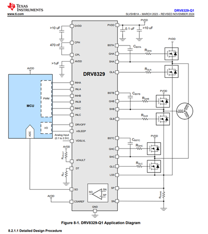
Other Parts Discussed in Thread: DRV8329, DRV8329-Q1

Tool/software:

Hi expert,

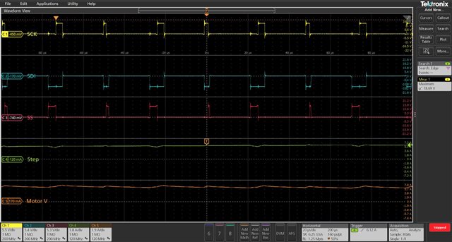
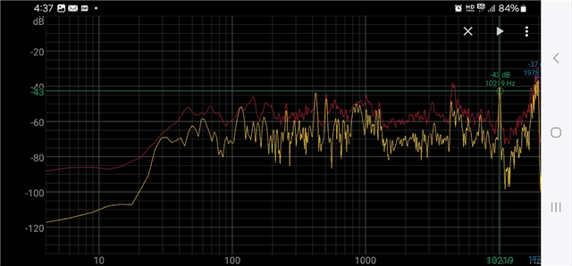
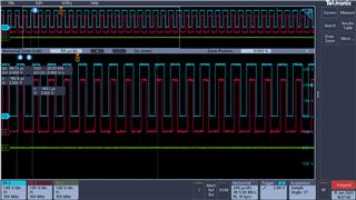
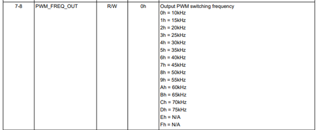
When the motor rotates, I hear high-frequency sounds in the 5khz and 10khz frequency range. What is this?

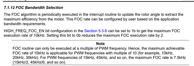
And could this feature possibly cause noise?

MCUs from other companies with the same motor do not produce such high-frequency sounds.

I think this is a software issue.

The software uses the same algorithm used in the example: C:\ti\mspm0 sdk_2_03_00_07\examples\nortos\LP MSPM0G3507\motor_control_pmsm_sensorless_foc\sensorless-foc DRV8329.

Please check this issue, and let me know if you need more information.

Best regards,

Donguk

  • Hi Donguk,

    Are you using a TI board or a custom board for your tests?

    Regards,
    Luke

  • Hey Donguk,

    What is your PWM switching frequency?

    Best,

    Akshay

  • Hi Akshay,

    Before speaking,

    This is off-topic, but Table 5-28 on page 36 of the MSPM0 Sensorless FOC Tuning Guide (Rev. B). According to CLOSED_LOOP1 Register Field Descriptions,

    Number 2 is said to be 20kHz, but the actual C:\ti\mspm0 sdk_2_03_00_07\examples\nortos\LP MSPM0G3507\motor_control_pmsm_sensorless_foc\sensorless-foc DRV8329. If you check configTables.c in the example, number 2 is 16kHz.

      -> i Think that must be fixed.

    Anyway, back to the point, I am using 20kHz.

    Best regards,

    Donguk

  • Hi Luke,

    We use custom borad.

    In a similar circuit, the MCU and gate driver were changed to MSPm0g3507 and DRVV8329, respectively, and only minor circuit changes were made accordingly.
    If I rotate the motor with another MCU with a similar circuit, the same sound does not occur.
    I think this is a software issue and not a hardware issue.

    Best Regards,

    Donguk

  • Hey Donguk,

    Would you be able to capture a waveform showing the phase voltage and phase current for a few PWM switching cycles?

    I am wondering if there is a specific noise profile that is visible which tracks with the 5k and 10khz noise.

    Best,

    Akshay

  • Hey Akshay,

    Since there are only two current probes, the current was measured only for phases A and B.

    I couldn't find anything that was producing the sound.

    I'll also send you some information about the sound I'm hearing.

    High_frequency.m4a

    I will also send you the results taken with a noise meter.

  • Hey Donguk,

    Could you capture the waveform at 100us per div, if there is an motor commutation issue leading to noise then if should be present every 100us (10kHz)?

    Best,

    Akshay

  • Hi Akshay,

    There is no noise occurring at 100us cycles on the 3-phase voltage/current waveform.
    Could this be a problem with the drv8329 gate driver?
    The ICs on my controller PCB are MCU, Gatedriver, LIN transceiver, and mosfets.
    When I apply 12V power, I hear a slight noise. I suspect that the noise is amplified when the motor rotates.
    When I applied 3.3V to the MCU using JTAG, there was no noise, so I excluded the MCU as a suspect causing the noise.
    Also, when I rotated it in debugger mode using XDS110 without using LIN communication, there was a loud noise, so I also excluded the LIN transceiver as a suspect.
    The only suspects left are the mosfets and gatedriver, but looking at the mosfets waveform, it doesn't seem to be the mosfets.

    Best,

    Donguk

  • Wait a minute, our product's PWM cycle is 20kHz, but looking closely at the waveform, the PWM signal comes out at a cycle of 40kHz, and the waveform seems to be the same every 20kHz. Could these pulses that come out in different shapes every 20kHz be the cause of the sound?

  • Hi Donguk,

    Where are you configuring the PWM frequency? Are you setting the pwmFreqOut to a different value? or using the setUserDefaultMotorParameters() function to adjust your closeLoop1 register?

    Regards,

    Luke

  • Hi Luke,

    We are using it this way.

    Regards,

    Donguk

  • This is something I discovered during my experiments.

    I don't know if it's a problem with the DRV8329 gate driver, but when I checked the phase voltage, All outputs were equal to the applied voltage (12V).

    Channels 1, 2, 3 are the outputs of a, b, c.

    There is no problem in running the motor, but I am wondering if this means that the high side is always open.

  • Hi Donguk,

    Wait a minute, our product's PWM cycle is 20kHz, but looking closely at the waveform, the PWM signal comes out at a cycle of 40kHz

    When the PWM frequency set as 20kHz, there current ripple frequency will be twice as the PWM frequency, due to it is 7 step SVPWM, which means that the current will switch twice within a PWM cycle.

    Normally, these two waveform need to be same. While, DRV8329 is a single shunt solution, so it will do phase shifter to reserve enough current smapling window to get both phase current. And yes, this migh bring additional noise. [Updated: I think this only occurs at high speed.]

    My question is that, for the other board, is its shunt resisitor also single shunt? And, is its PWM frequency is also 20kHz?

    Sometimes, the deadtime will also make the impact on the noise, so is there any difference on this parameters setting with these two different board? [combine the software setting and gate driver setting]

    Generally speaking, for noise issues, in the software part, the tuning method is to “Adjust the current loop bandwidth to reduce the current response speed (equals to decrease kp/ki of the current loop), which can suppress partial noise.”

    By the way, this is a typo in the tuning guide, we will fix it in future version.

    This is off-topic, but Table 5-28 on page 36 of the MSPM0 Sensorless FOC Tuning Guide (Rev. B). According to CLOSED_LOOP1 Register Field Descriptions,

    B.R.

    Sal

  • Hi Sal,

    That's right. The product that used the MCU of another company that was in use also uses 1 shunt 1mΩ and operates at the same 20kHz. 

    B.R.

    Donguk

  • Got it.

    So, what's its current waveform looks like?

    B.R.

    Sal

  • Hi Sal,

    Sorry for the late reply. I'm on vacation until today.

    This is the current waveform shape of a third party.

    This is the current waveform shape of the Ti MCU.

    This is the result of being powered by the same 14V/0.6~0.8A DC power supply, and as shown in the figure, the amplitude and shape are quite different.
    In my opinion, Ti's current waveform is better, but the gate waveform and the audible noise are not as good as third party.

    https://e2e.ti.com/support/motor-drivers-group/motor-drivers/f/motor-drivers-forum/1469460/drv8329-q1-overshoot-is-detected-on-output-when-startup

    -> gatedriver wave

    We are suspecting the drv8329 gate driver as the source of the noise. Can you please tell me why the output voltage of each phase is 12V (battery voltage) when the motor as asked above is not running (i.e. both high side and low side are off)?

    B.R.

    Donguk

  • If you would like to see if there is a hardware problem, please refer to the circuit I emailed you on January 16th.

    If you have any concerns about what might be causing problems with the hardware design, please respond via email rather than the forum.

    We designed the hardware based on the following reference circuit:

    -> DRV8329-Q1 4.5 to 60V Three-phase BLDC Gate Driver datasheet (Rev. A)