This thread has been locked.

If you have a related question, please click the "Ask a related question" button in the top right corner. The newly created question will be automatically linked to this question.

DRV8329-Q1: Overshoot is detected on Output when startup

Part Number: DRV8329-Q1

Tool/software:

Dear TI experts,

My customer tests DRV8329AQRGFRQ1 on their own PCB.

While testing they found overshoot on output waveform when startup, while competitor does not have. Please see the waveform below ;

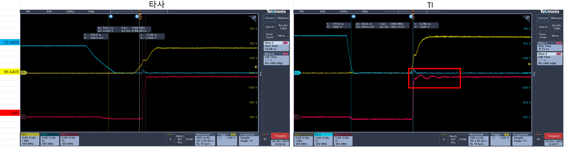
(Left is the waveform of competitor, Right is the waveform of DRV8309-Q1. You can see the overshoot in the red square box.)

Could you give me some ideas to remove this voershoot?

Please check this issue. Thanks.

Best regards,

Chase

  • Hey Chase,

    What is the target VDS rise/fall time for the customer?

    What MOSFET are they using and what gate resistor value have they utilized? (If you can share the schematic then I can check this.)

    From what I can see the customer is using a very fast gate current resulting in the phase voltage overshoot. We typically recommend 200ns rise time and 100ns fall time for VDS for fast switching applications (how much overshoot will also depend on layout and board design).

    Based on the time scale in the waveform it seems that the TI solution is being made to switch much faster. Could you confirm that the rise time spec shown in the waveforms 54.08ns and 15.72ns refer to the VDS rise time? If so then the two solutions are not targeting the same VDS slew rates.

    In order to limit the overshoot, the customer, can add gate resistors to slow down the slew times as the ones in waveforms are very fast. (linking an E2E FAQ on gate resistor sizing below), and also look into adding RC snubber in their board (linking an E2E FAQ on the topic below).

    1) https://e2e.ti.com/support/motor-drivers-group/motor-drivers/f/motor-drivers-forum/1163372/faq-gate-resistor-calculator-for-drv8328-drv8329

    2) https://e2e.ti.com/support/motor-drivers-group/motor-drivers/f/motor-drivers-forum/991693/faq-proper-rc-snubber-design-for-motor-drivers

    These should help with the ringing but fundamentally this seems to be coming from a very fast switching.

    Best,

    Akshay

  • Dear Akshay,

    I got feedbacks from my customer. Please check the comments below ;

    - They tested gate resistor from 4.7 to 30 ohm, but they could not find much differences, just found similar overshoot.

    - They already have RC snubber on schematic.

    - target VDS rise/fall time : under 60ns

    target Dead Time : 500ns

    - MOSFET : ONSEMI / NVMFS5C442N / RDS(on) : 2.3mΩ MAX,  Gate resistor : 4.7Ω

    Please check the details, and give me some advice.

    Best regards,

    Chase

  • Hey Chase,

    60ns is extremely fast , so I can see why there might be some overshoot.

    Based on the time scale in the waveform it seems that the TI solution is being made to switch much faster. Could you confirm that the rise time spec shown in the waveforms 54.08ns and 15.72ns refer to the VDS rise time? If so then the two solutions are not targeting the same VDS slew rates.

    Any update on this?

    Best,

    Akshay