This thread has been locked.

If you have a related question, please click the "Ask a related question" button in the top right corner. The newly created question will be automatically linked to this question.

TMDSCNCD263P: OSPI bootloader not working/executing from flash

Part Number: TMDSCNCD263P
Other Parts Discussed in Thread: TCA6424, TCA6416, UNIFLASH

Tool/software:

Hello, 

I am trying to get the TI example for OSPI communication working. There seems to be an issue with the OSPI driver setup in the flash_diag example. 

The aim is to get the example with XIP (benchmarks/ocmc) working, but I was having issues with this. As such, I switched to ensuring OSPI flash communication works as intended.

Hardware: TMDSCNCD263P, ControlCard version PROC159A

SDK version: mcu_plus_sdk_am263px_10_01_00_31

Steps done so far:

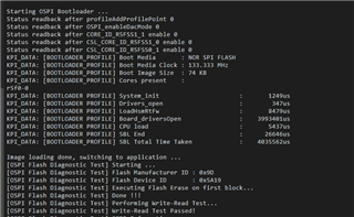
1. Run ospi_flash_diag example (C:\xx\mcu_plus_sdk_am263px_10_01_00_31\examples\drivers\ospi\ospi_flash_diag\am263px-cc\r5fss0-0_nortos) without bootloader (DEV_BOOT mode). Result: This runs OK, I can see same UART output as example.

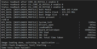
2. Run ospi_flash_diag example with sbl_ospi.release.tiimage under "C:\ti\mcu_plus_sdk_am263px_10_01_00_31\tools\boot\sbl_prebuilt\am263px-cc\". Flash sbl_ospi with offset 0x0 and ospi_flash_diag with offset 0x81000 as intended. Result:


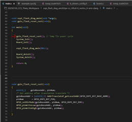
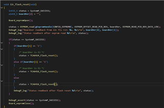
3. Debugged bootloader in i2c_flash_reset, with code below. Debug output from the EEPROM read returns 0, and so the default function goes into TCA6416_Flash_reset, which is incorrect as that chip was only present on the earlier version  of the ControlCard (version PROC159E2). There's a question why the EEPROM does not return the correct value for boardver (0), but this this code probably needs updating so the default function is TCA6424_Flash_reset.

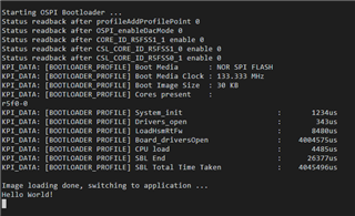
4. Created custom bootloader with this step from #3 above. Flash this using UniFlash together with helloWorld application. Run application from OSPI. Result: serial output is OK. (so custom bootloader is OK, OSPI load from boot seems to work also)

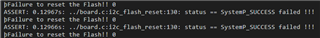
5. Flash custom bootloader and ospi_flash_diag example from #1. Now, we get one step further as we enter application, but fail on the first step of communicating with the flash chip from there.

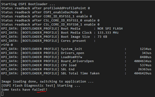
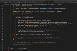
This implies we fail on execution of the first OSPI_norFlashReadId(). I have not continued debugging but it would seem like there is something fundamentally wrong with OSPI modes/sequencing or similar. Could a member of TI go through this last step and verify the OSPI SBL works OK with the Flash Diag example?

Thanks,

Rens

  • Hi Rens,

    Apologies you had a face this issue, we identifued this bug lates last week and we are working on making the updated release to fix it. 

  • The issue is happening due to boards version mismatch, As the new revision of Control card has similar flash reset mechanism as am263px-lp.

    So for the meanwhile you can use the following workaround:

    1. In syscfg(examples\drivers\boot\sbl_ospi\am263px-cc) add the following GPIO pin:

    gpio1.pinDir = "OUTPUT";
    gpio1.$name = "GPIO_OSPI_RST";
    gpio1.defaultValue = "1";
    gpio1.GPIO_n.$assign = "EPWM11_B";

    2. Then in SBL OSPI example replace the file examples\drivers\boot\sbl_ospi\am263px-cc\r5fss0-0_nortos\board.c with the file:

    C:\ti\mcu_plus_sdk_am263px_10_00_00_35\examples\drivers\boot\sbl_ospi\am263px-lp\r5fss0-0_nortos\board.c

    3. Rebuild the example

    For flash example same thing needs to be done,

    Let me know if this helps.

  • Hi Nilabh,

    Thanks for the rapid response. For anyone else looking at this, be sure to select 'gpio1.GPIO_n.$assign = "EPWM11_B/J1"'; (as opposed to 'EPWM11_A').

    With this reset now connected, the custom sbl runs as expected. However, when I try to also flash in the example ospi_diag application, I was getting the same issue as before, where the Application was not running:

    I noticed there were quite a few different settings for OSPI between the ospi bootloader and flash diag application. For example, the ospi clock freq is set to 80MHz as opposed to the 133.3 MHz in ospi bootloader, mode is 1s-1s-1s vs 8d-8d-8d etc. 

    I have tried to mostly align ospi settings but think the ospi flash diag example contains some repeated secondary initialisation parts of the OSPI module, so expect a resource lock or similar is causing a problem.

    To resolve this, for testing I can add a flash chip power cycle on start of application boot, resetting the ospi interface. This allows the flash diag example to proceed as expected, booting from OSPI.

    However - this raises some questions around OSPI initialisation, with respect to XIP.

    1 - At end of bootloader initialisation, just before jump to application, the ospiHandle instance is not closed/de-initialised. From the application, we want to access the OSPI interface. Is this handle accessible from the application, or does (every core) need its own instance for the ospiHandle? Or potentially do we need to remove the resource lock from OSPI driver before starting the application?


    2. With several cores active (r5fss0-0/r5fss0-1 in lockstep, r5fss1-0 & 1-1 separate) - what is the way to ensure cores cannot access OSPI concurrently - does this need implementation of a queue system?

    3. Are there currently recommended settings to use for OSPI (freq, mode etc), especially for usage for XIP?

    4. Next step is to get ocmc_benchmarking example project working, but multiple cores make initial configuration less clear. Is there an example project for single-core XIP running?

    Thanks,

    Rens

  • I noticed there were quite a few different settings for OSPI between the ospi bootloader and flash diag application. For example, the ospi clock freq is set to 80MHz as opposed to the 133.3 MHz in ospi bootloader, mode is 1s-1s-1s vs 8d-8d-8d etc. 

    OSP{I diag example works with minimum configuration as it is expected to test if flash is working on not and also read sfdp table which is used to get all supported flash RW combinations.

  • - At end of bootloader initialisation, just before jump to application, the ospiHandle instance is not closed/de-initialised. From the application, we want to access the OSPI interface. Is this handle accessible from the application, or does (every core) need its own instance for the ospiHandle? Or potentially do we need to remove the resource lock from OSPI driver before starting the application?

    Hi Rens, You do not need OSPI handle for XIP execution, SBL sets it up correctly, so next all the  code (instructions) present in flash can be accessed by direct memory mapped mode by CPU or DMA.

  • 2. With several cores active (r5fss0-0/r5fss0-1 in lockstep, r5fss1-0 & 1-1 separate) - what is the way to ensure cores cannot access OSPI concurrently - does this need implementation of a queue system?

    Are you asking this wrt to XIP or normal flash read and writes?

  • 3. Are there currently recommended settings to use for OSPI (freq, mode etc), especially for usage for XIP?

    4. Next step is to get ocmc_benchmarking example project working, but multiple cores make initial configuration less clear. Is there an example project for single-core XIP running?

    Thanks,

    You can use the documentation to enable just simple hello world example with XIP:

    software-dl.ti.com/.../BOOTFLOW_XIP.html

  • Hi Nilabh, thanks for the follow up.

    So far, I've had a single core project running using XIP, then subsequently also ran ocmc_benchmark, so heading in the right direction.

    Regarding this:

    Are you asking this wrt to XIP or normal flash read and writes?

    This was potentially for the case that core 2 (r5fss1-0) or core 3 (r5fss1-1) need to read/write certain variables to the flash whilst core 0 (r5fss0-0) is running some/all code using XIP - also from flash. 

    The absolute easiest way to handle this would be to ensure that core 2 or 3 only ever use variables from ram - never from flash.

    However, if other cores do need flash access, I envisage a process something along these lines:

    - Setup shared (r/w) memory region between core 0 and core 2 (or core 3), containing all flash variables which core 2 (or 3) needs access to

    - Setup IPC to trigger a request from Core 2/ core 3 to core 0 whenever a block flash read/write is required

    - Core 0 enqueues this request and handles/executes to flash driver when possible - i.e. at a point where code execution is primarily from ram, not from flash

    The point where this 'normal' flash read/write would be possible isn't really clear to me. Would you need to build in certain code regions to just execute from ram to allow time for normal flash read/write requests in between XIP reads? Or would you need to rely on a big cache e.g. RL2 cache to store a certain amount of symbols before so there is a buffer of sorts where code is only run from the cache, leaving time for the normal flash r/w?

    Or maybe I'm missing a step - would you suggest to do this another way?

    Thanks, Rens

  • So far, I've had a single core project running using XIP, then subsequently also ran ocmc_benchmark, so heading in the right direction.

    This is good to know.

    For XIP your approach sounds good, as this way only one core has access to OSPI driver thus less over head of synchronization.

    This was potentially for the case that core 2 (r5fss1-0) or core 3 (r5fss1-1) need to read/write certain variables to the flash whilst core 0 (r5fss0-0) is running some/all code using XIP - also from flash. 

    This is better done via IPC.

    So there are two ways you can read from flash:

    1. Direct access mode(memory mapped mode), also used in XIP

    2. Indirect access, where you send some commands via OSPI controller and then receive the response back.

    Hope this clarifies the doubt.

  • Ok thanks Nilabh. I'll do some more experimentation on this topic and raise another query if there's further issues. Thanks so far.

    Kind regards, Rens