This thread has been locked.

If you have a related question, please click the "Ask a related question" button in the top right corner. The newly created question will be automatically linked to this question.

MSPM0G3507-Q1: Repeated input pin damage (shorted to VDD)

Part Number: MSPM0G3507-Q1
Other Parts Discussed in Thread: TPS7B69-Q1

Tool/software:

Hi,

I would like to ask for your help with an issue we've been dealing with for a while now. Many of our regulator units died during testing (sometimes simply while laying on a table with nothing connected to them, apart from power and CAN bus).

Brief device description:

Electric water heater regulator, communicating over CAN bus.

2 PT100 temperature sensors, a flowmeter and a 3-phase triac regulator are connected to the device via a screw terminal block.

The common factor among all of the cases seems to be that after the unit gets destroyed, VDD and pin PA25 are connected to ground via a low impedance inside the MCU - most of the time it's not a dead short (10s of ohms), but VDD and PA25 are virtually shorted together. This leads me to believe, that one of the protective diodes on the pin is destroyed. I tried testing the pin with mild electrostatic discharges, but this had no effect. Connecting 24 V to the pin resulted in it shorting to VDD, essentially simulating the above mentioned state.

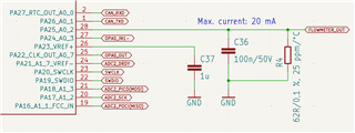
This pin is used as an input to the ADC and is a part of a 4 - 20 mA current loop, sensing the output of the flowmeter. The issue sometimes happens even when there's nothing connected to the terminal (FLOWMETER_OUT in the schematic).

I plan to test it with a more powerful static discharge tomorrow, but apart from that, I'm running out of ideas what could be the cause of this problem.

Is there any possibility, that a misconfigured pin can lead to a situation like this?

main_syscfg.zip

  • Is there a relay or something up stream in the current loop? I would suspect a transient.

    This thread has a lot of good ideas

    https://e2e.ti.com/support/microcontrollers/msp-low-power-microcontrollers-group/msp430/f/msp-low-power-microcontroller-forum/1472205/msp430f5438a-uart_esd_protection

  • Hi Jakub,

    The maximum current that you can put in / pull out of PA25 (standard drive IO) is 6mA. The maximum voltage the pin is rated for is also the value Vdd+0.3V. You can damage the pin by exceeding either one of these limits.

    I see you mention that this sometimes occurs to devices that have nothing connected to the pins? Are you saying that you have boards that have never had anything connected there and get this issue where PA25 appears to be shorted to VDD?

  • Hi,

    there is no relay or any other inductor in the circuit. The issue can happen even if there's nothing connected to the input terminal of the board and as far as I can remember, never has been.

    I tried setting the pin as an output with logical high, in which situation it sourced roughly 30 mA into the 62 ohm resistor. Then I left it running like this for around 15 minutes without any signs of damage (the chip only heated up slightly). I repeated the same test with a direct short to ground, but it only pulled 30 mA from the pin. Again, no damage.

    The pin also survived multiple direct pulses from a piezoelectric igniter from a lighter, even when the ground of the igniter was connected to the ground or positive terminal of the board, which honestly impressed me. I am still hesitant to rule out the static discharge as a cause for the trouble, but this test showed that the MCU is rather resilient.

    The particular chip that I tested was also able to run on 5 V, despite it's absolute maximum being 4,1 V.

    The whole system is powered from 24 V, so I wanted to test what will happen, if for example the TPS7B69-Q1 fails to regulate the voltage for the MCU and puts the full input voltage onto the output. While the VDD and VCORE pins shorted to ground, no IO pins show any signs of damage (I'm measuring around 0.7 V from pins to VCC and GND and ohmmeter shows high impedance).

  • Note that a short to VDD is likely caused by a short in the ESD diode. It has an absolute max rating of 2 mA. It can be forward biased if the pin is taken to a voltage a half volt or so above VDD. Note that if VDD is zero, any voltage on the pin can forward bias the diode.

    What usually happens is that the chip gets powered via the ESD diode from the GPIO to the VDD rail, much to the consternation of folks not expecting it. (Like me!)

  • How are you testing to see that there is a short from the pin to VDD?

    What percentage of devices do you see this on, and is it only occurring on boards that you've supplied with the 24V supply (understood that you have regulators and step this down)?

  • Good point with the forward biasing when VDD is 0. It still puzzles me where would the voltage come from, when there's nothing connected to the pin, though..

  • I'm testing the pins with a diode tester and an ohmmeter.

    We have only made a couple of boards so far (less than 20), but it happened at least 5 times already.

    I can't tell for certain if it only happens when the 24 V supply is connected, but this is when the issue fully manifests itself, because the excessive current blows the input fuse (100mA, delayed). I guess it is possible that it can happen even during programming when the main power is disconnected, but on the other hand, I have never noticed the programmer switching off due to overcurrent.

  • I would recommend that when you assemble more boards (and perhaps reassemble one of the broken ones with new silicon) you probe PA25 when you power the device on to monitor for whether the pin is exposed to potentially damaging conditions. It is very unlikely that the device is being damaged before any power is supplied to your board, you can also test for a short before and after powering each board for the first time. 

    I would also recommend reviewing your hardware design and check for things that could cause exposure to high voltage, or that could pull too much current through the pin and damage the diode. I see above that you show the schematic for the one pin, you may want to check the full power supply. 

  • I added a 10k resistor in series with the pin and it looks like it doesn't affect the measured values in any way. We'll make a new revision of the board and see if it helps (would be weird if it didn't).

  • Sure, that could help here as well. Feel free to resume the thread if you need further assistance on this issue.