Part Number: MCU-PLUS-SDK-AM243X
Other Parts Discussed in Thread: SYSCONFIG
Tool/software:
Hi experts,
We tested the flash-read waveform of OSPI DQs/DS/CLK Pins on 8d-8d-8d mode, and found it's very inefficiency. Is where any way to improve at present and any plan to update SDK?
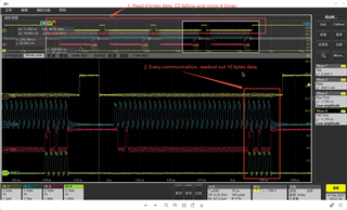
#1. Read x consecutive bytes, will trigger x times transfer instead of 1 time
#2. Every communication, although only read 1 byte, actually triggers 10 bytes CLK.
Question #1 and #2 show in the below picture: waveform of read 4 bytes from ospi flash.
In fact, one time ospi transfer is enough.
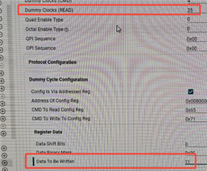
# 3. Default dummy Cycle is tow long at low frequency(25MHz). When 25MHz, 25->6, 11->0 is enough。
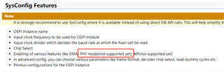
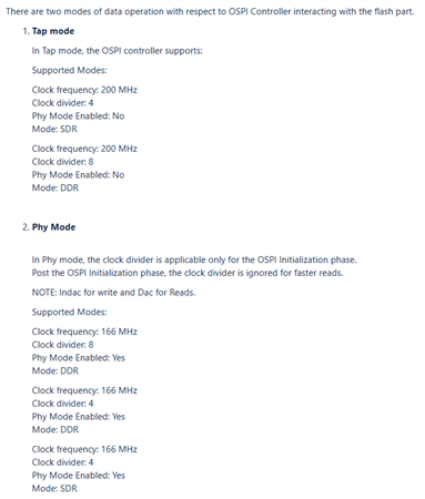
# 4. Unsupport high frequency. Modify OSPI frequency higher than 50Mhz such as 100MHz(200MHz/2) and enable PHY mode, project can't work. PHY mode and high frequency unsupport right now and is there a plan for when to support?