Part Number: MSPM0G1506
Tool/software:
Hi,
I managed to flash my application via UART BSL on my board with default UART pins (Tx = PA 10, Rx = PA11).
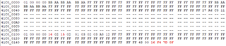
(Arrow marks first command from the BSL-Master)
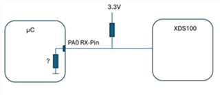
But when I try to use my board with non-default UART pins (Tx = PA 0, Rx = PA1) it fails.
First step was to flash a SW which configers the BCR and BLS for PA0 and PA1.


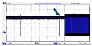
(Arrow marks first command from the BSL-Master)
Why the Rx-Pin voltage drops to another level when the µC recives the first message from the BSL master?
We have build up 200 samples of our product with none-default UART so it is verry importent for me to get the BSL up and running.
Thanks in advance
Matthias