This thread has been locked.

If you have a related question, please click the "Ask a related question" button in the top right corner. The newly created question will be automatically linked to this question.

MSPM0G3507: Detect 16bit timer overflow

Part Number: MSPM0G3507
Other Parts Discussed in Thread: MSP430F5324,

Tool/software:

Hi expert

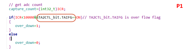
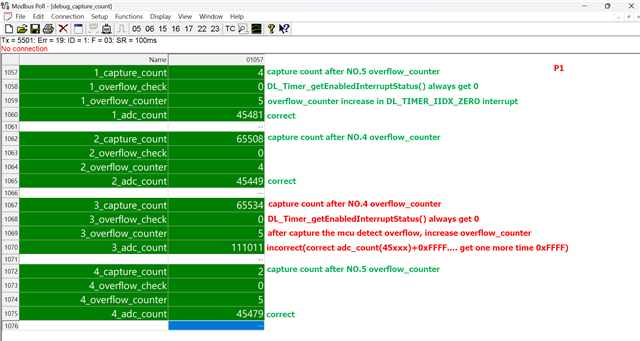
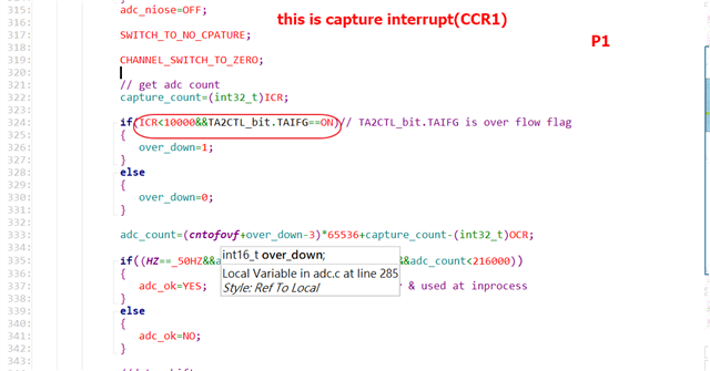
in my previous project(MSP430F5324), i use TAIFG bit to detect timer overflow(P1),

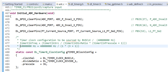
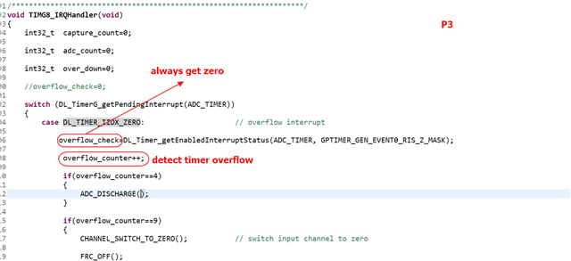
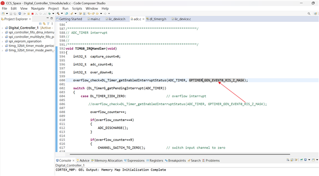
now in current project(MSPM0G3507) which register can meet my need?

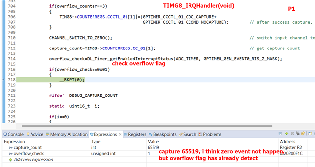
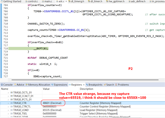
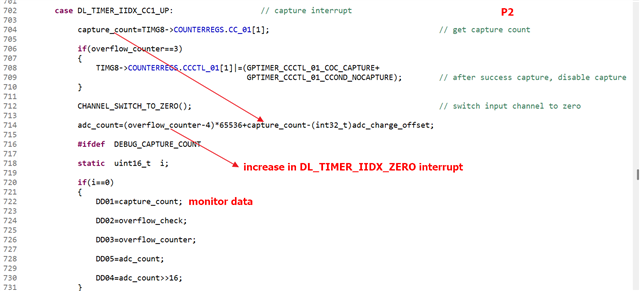
Is TOV bit(P2) available?

P2.pdf

  • Hi, 

    These are invalid information, delete to avoid further misunderstanding...

    Regards,

    Helic

  • I think TAIFG corresponds with the LOAD event (down-counting) or ZERO event (up-counting) [Ref TRM (SLAU846B) Figs 27-6, 27-10]. 

  • Hi,

    sorry for my mistake, is seems there is no overflow interrupt of MSPM0's time.

    Regards,

    Helic

  • Hi Bruce

    thanks for your reply, i use up counting mode(TIMG8) and enable zero & ccr0(compare) & ccr1(capture) interrupt,

    and my timer is free running, it will generate several overflow in a process.

    in my ideal condition : when i capture a few count(maybe<10) then checking overflow flag, if flag=1

    i will know that the timer has just overflow and this data(capture value) needs special processing.

    but in  actual condition when i capture 65519 and detect the overflow flag at the same time(P1), I am confused,

    and the current CTR value also strange(P2).

  • Hi, 

    One tips from my side:

    Please pay attention to the TIMER_ERR_01

    https://www.ti.com/lit/pdf/slaz742

    Regards,

    Helic

  • Hi Helic

    thanks for your reply, i think my capture value is correct, i just want to know 

    if the TIMER has just overflowed when capturing a value less than 10.

  • Hi, 

    For real time debug, please try to use set/clear GPIO to debug.

    In a logic analyzer, it's more easy to confirm the sequence between gpio, timer interrupt and overflow.

    I am not sure whether have some delay between __BKPT(0) and Zero/Load interrupt.

    Regards,

    Helic

  • 1) What is the tick rate for your timer (i.e. prescale)? If it's /1, it wouldn't surprise me if (65536-65519)=17 CPU clks (MCLKs) elapsed between the capture and the interrupt (MIS) fetch. This is very tight timing.

    2) The timer (normally) keeps running during a breakpoint, so you can't really trust the CTR value that the debugger fetches. See also:

    https://e2e.ti.com/support/microcontrollers/arm-based-microcontrollers-group/arm-based-microcontrollers/f/arm-based-microcontrollers-forum/1490313/mspm0l1306-how-to-stop-timer-counter-while-cpu-execution-is-halted-for-debug-when-a-breakpoint-is-hit-in-mspm0l1306

    [Edit: Clarified the latency gap.]

  • Hi Bruce

    thanks for your reply, my timer clock is 10MHz, MCLK=40MHz, i can understand if the timer keep running in debug,

    but i still confused because the breakpoint set in line 718, if program stop in breakpoint, the capture value

    and overflow_check should not be affected by timer running and the result are capture value=65519 and overflow_check=1,

    I don't know why I get this result, in my opinion i should get  capture value=65519 and overflow_check=0 or

    capture value=10 and overflow_check=1.

  • The capture took place (presumably) before the ISR was called, effectively "freezing" the CTR value at that moment. The CTR kept ticking (and evidently overflowed) between then and the time you fetched the MIS interrupt flag.

    This race was also possible on the MSP430, but perhaps the path lengths were shorter.

    Are you using the overflow as (a) a means of extending the timing range (overflow-counting) or (b) a timeout mechanism? If it's the latter, what I usually do is set the other CC register (compare mode) to the capture value, and if the compare ever triggers that's a timeout.

    If all you're measuring is the time between captures (subtracting consecutive capture values), an overflow doesn't require special treatment, due to the nature of unsigned arithmetic.

  • Hi Bruce

    thanks for your reply, i recently tested and looked for a solution, please see my explain as below.

    1. This project is a dual-slope ADC and i use overflow as (a) a means of extending the timing range (overflow-counting) to as discharge count calculate, in discharge process the timer will generate several time overflow, the P2 is my adc_count formula and monitor data build in capture part.

    2. P1 is the 4 times monitor data, you can see in 3rd I got the wrong adc_count,capture_count=65534 but get new overflow_count(5), in previous project(MSP430) I rely on TAIFG to eliminate 0xFFFF(new overflow_count) but in this project I can’t use DL_Timer_getEnabledInterruptStatus() to detect overflow even if I put this in overflow interrupt first line(P3) , that's frustrating

    3. eventually I used the filter technique to eliminate this 0xFFFF.

  • In P3, you use DL_TimerG_getPendingInterrupt function.

    This function will read IIDX register, by reading IIDX, interrupt will be auto cleared by reading action.

    You need put your overflow_check ouy of switch, read it at the first line of Timer Handler.

  • Hi Helic

    thanks for your replay, i move DL_Timer_getEnabledInterruptStatus() from switch inside to switch outside, i still can't get

    overflow indicate.

    The parameter overflow_check update in this address and assign to monitor parameter in DL_TIMER_IIDX_CC1_UP(capture interrupt).

  • Can you entering the code line 606 ~ 616?

    If this interrupt entered, that means Zero event is triggered.

    You can directly set overflow_check to true.

    In switch, it used DL_Timer_getPendingInterrupt which will read IIDX register.

  • Hi Helic

    thanks for your reply, of course i can enter 606~616 and i put some accumulator in zero event and i knowing i can use a flag to indicate overflow but i don't know when to clear this flag, so i must use DL_Timer_getEnabledInterruptStatus() to get overflow condition but DL_Timer_getEnabledInterruptStatus() still didn't work even if i put it in TIMG8_IRQHandler first line.

    This API is officially provided, i hope TI can teach user how to use this api correctly.

  • DL_Timer_getPendingInterrupt 

    M0 read IIDX register, please refer to TRM for how M0 handle the interrupt while reading this register.

    This register provides the highest priority enabled interrupt index. Value 0x00 means no event pending. Interrupt
    1 is the highest priority, IIDX next highest, 4, 8, … IIDX^31 is the least priority. That is, the least bit position that is
    set to 1 denotes the highest priority pending interrupt. The priority order is fixed. However, users can implement
    their own prioritization schemes using other registers that expose the full set of interrupts that have occurred.
    On each read, only one interrupt is indicated. On a read, the current interrupt (highest priority) is automatically
    cleared by the hardware and the corresponding interrupt flag in [RIS] and [MIS] are cleared as well. After a read
    from the CPU (not from the debug interface), the register is updated with the next highest priority interrupt, if
    none are pending, then it should display 0x0.
    F

    27.3.11 IIDX (Offset = 1020h) [Reset = 00000000h] in G series TRM https://www.ti.com/lit/ug/slau846b/slau846b.pdf

  • If you're fetching MIS:Z on every interrupt, but only checking it in the CCU1 case, then it will (almost) always read as 0, since in the IIDX register Z has priority over CCU1. Supposing both Z and CCU1 are pending, the sequence would be:

    1) Enter ISR for Z, fetch MIS:Z -> overflow_check

    2) Read IIDX=Z, clear MIS:Z

    3) Enter ISR for CCU1, fetch MIS:Z  ->overflow_check which was just cleared in (2)

    4) Read IIDX=CCU1, (clear MIS:CCU1), look at overflow_check which is now 0

    Your original code ignored a TAIFG which occurred with a capture up near the high end of the counting range ("if (ICR<10000&&TAIFG_set)"). Could you continue to do that?

    [Edit: I think I'm catching up here. I suspect your original code used the (MSP430) IV register, where CCR1 has priority over TAIFG (opposite to IIDX). There might be a way to reverse the "if" test above. Alternatively, you can just dispense with the IIDX register and decode the bits yourself. A common idiom I use is:

      uint32_t mis = TIMER->CPU_INT.MIS;        // Snapshot all
      TIMER->CPU_INT.ICLR = mis;                // Clear all
      if (mis & GPTIMER_CPU_INT_MIS_CCU1_MASK ) // Check CCU1 first
      { and so on }

  • Unsolicited: Possible alternatives to overflow counting:

    1) Increase the prescaler, in effect trading resolution for range [available within limits on MSP430]. 

    2) Use a 32-bit timer (TIMG12) [not available on MSP430]. (This costs you the Only 32-bit timer, but it's pretty easy to do.)

    3) Use the Event system to adopt a second (16-bit) timer as an overflow counter [not available on MSP430]. This would take 2x Event (provider/subscriber) connections from TIMG8 to the other timer: (1) feeding the Z Event into the other timer's CCCTL_01[0].ACOND so its CTR ticks and (2) feeding the CCU1 (capture) Event into  the other timer's CCCTL_01[1].CCOND (capture) so it captures the overflow CTR->CC_01[1] at the same time. [Disclaimer: I haven't actually tried this.]

    [Edit: Minor clarification]

  • Hi Bruce

    thanks for your reply

    Your original code ignored a TAIFG which occurred with a capture up near the high end of the counting range ("if (ICR<10000&&TAIFG_set)"). Could you continue to do that?

    yes, please check P1, this is our previous way(MSP430), i have already considered the situation of capture near the high end,

    in this project(MSP430), in capture interrupt to check TAIFG(overflow), it is feasible but i can't get same result in M0G.

    As your mentioned the priority of interrupt in M0G and MSP430F5 are opposite, that is why i can't detect overflow flag(zero

    event) in capture interrupt(CCU1), am i right?

    priority.pdf

  • Yes. Your code fragment didn't show it, but if you were using the (MSP430) TA2IV register (in this particular race), the CCR1 interrupt would be presented first, and the TAIFG would still be set. That wouldn't be true for the (MSPM0) IIDX.

    [I mentioned trying to reverse the test, but I couldn't come up with a (reliable) way to do that.]

    I suspect the simplest solution is to read the MIS register directly (as outlined above), and deal with the interrupt conditions in the order that works for you. (I frequently end up doing that for the MSP430 as well, when the fixed IV prioritization is inappropriate.)

  • Hi Bruce and Helic

    thanks for help me to clarify this problem.