This thread has been locked.

If you have a related question, please click the "Ask a related question" button in the top right corner. The newly created question will be automatically linked to this question.

AM263P4-Q1: Error in writing values to L2OCRAM_BANK4 (0x70200000) and L2COCRAM_BANK5 (0x70280000)

Part Number: AM263P4-Q1
Other Parts Discussed in Thread: SYSCONFIG, AM2634, AM263P4, UNIFLASH

Tool/software:

Hello, 

I'm trying to use the memory region from 0x7020 0000 to 0x702F FFFF as shared memory. As none of the examples define this region in the MPU, I added an entry in the sysconfig as below: 

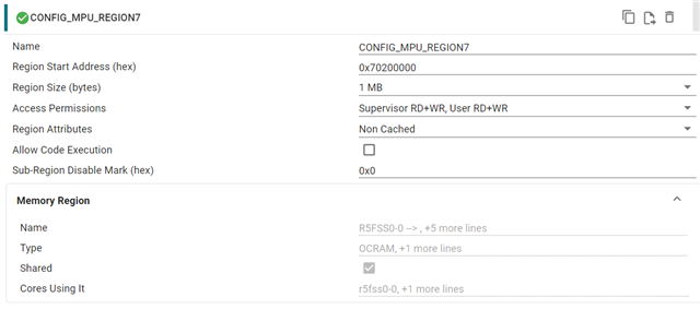
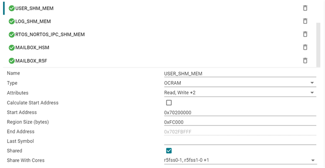
and then in the memory regions, set it as shared:

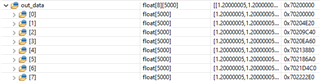
In the code, I have a variable defined as follows:

#define OUTPUT_BUFFER_LENGTH 5000
#define ANALOG_CHANNELS_PER_CORE 4
volatile float out_data[ANALOG_CHANNELS_PER_CORE * 2][OUTPUT_BUFFER_LENGTH]__attribute__((section(".bss.user_shared_mem")));

and then I tried to initialize the array to 0:

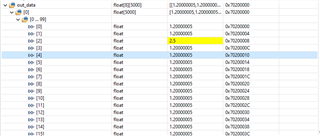
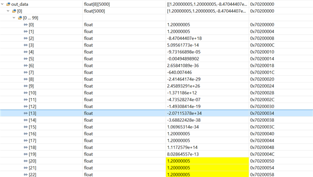
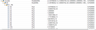
for(uint16_t i = 0; i < (ANALOG_CHANNELS_PER_CORE * 2); i++)
{
for(uint16_t j = 0; j < OUTPUT_BUFFER_LENGTH; j++)
{
out_data[i][j] = 0.0f;
}
}

The problem is not all values get sets to 0, if I pause the application and try to manually set the array values to 0, it still doesn't work! I wonder if that is a silicon issue? do I have a bad SOC? or a configuration issue? 

Update: I tested another board and got the same result, so it isn't a bad SOC.

  • Hi Ahmed,

    I tried the following steps:

    1. Import the empty multi-core project in CCS from MCU_PLUS_SDK for AM263Px.

    2. In core-0 syscfg, make the changes similar to the ones shared by you

    3. In the main function, add the for loop to populate the "out_data" buffer. (instead of 0.0f assignment, I assigned 1.2f values, since compiler will automatically assign "0"). See the below screenshot for the populated out_data buffer.

    4. On running this code, I am able to properly update the buffer values (manually from expressions window as well, see the below screenshot)

    I need your help in reproducing the issue. Can you please share your CCS Multi-core project or the steps to reproduce this issue?

    Regards,
    Shaunak

  • Hello Shaunak,

    I will replica your steps and also upload the project shortly. 

    Quick question, when you setup MPU, do you only have it for core0? I was under the impression that I have to do it for all 4 cores.

    Thanks

  • Hi Ahmed,

    Quick question, when you setup MPU, do you only have it for core0? I was under the impression that I have to do it for all 4 cores.

    In my case, I only configured MPU region and Memory configurator for core-0. Also, the nested for loop you run, are they on the other R5F core's code?

    Regards.
    Shaunak

  • I wonder if that is the problem, I will remove MPU from other cores! 

    and this loop is only for testing on core0 only.

    The rest of the code that is currently commented out uses spinlock to protect access to the out_data array. I will upload the full project when I reach my computer. 

  • Hello, 

    I replicated your steps, and I still get that same error

    as you can see some values got updated to 1.2f and some didn't! attaching the empty project example.

    empty_am263px-lp_system_nortos.zip

  • Just a an update, I tried changing the memories configuration around so the shared memory is in 0x70080000 with size of 512KB so memory bank 1, and core 1 OCRAM now is in bank 4. Now the array is accessed properly, but core 1 doesn't work. I wonder if this has anything to do with my part number, this is the part marking on the SOC:

    AM263P4ACOKFZCZQ1

    4AA6SQW G1

    867  ZCZ

  • Hi Ahmed,

    Thanks for sharing the project, I imported it, built and ran as it is without any modifications.

    I was able to run your code (in both debug and release modes) and get the expected results (everything assigned as "1.2" in the out_data array. Let me check if this is something to do with Hardware part numbers.

    Regards,
    Shaunak

  • Hi Ahmed,

    Can you please let me know if you are using AM263Px-LP with any specific hardware modifications or a custom board?

    Regards,
    Shaunak

  • Hi Ahmed,

    Another question, do you flash the application and run it, or are you just loading the .out file via CCS to both the cores and trying? For reference, I had SBL NULL flashed and set OSPI boot-mode, then via ccs connected and loaded .out files to R5F cores.

    Regards,
    Shaunak

  • Hello Shaunak,

    I'm using a custom board, as of now, SOP is set to devboot. This board was designed for the older AM2634, so it has a QSPI flash. But they should be compatible, right? 

    Is there a way to do that in DevBoot? I have 0hm resistors to switch to QSPI when development is done.

    Thanks again!

  • Hi Ahmed,

    This board was designed for the older AM2634, so it has a QSPI flash. But they should be compatible, right? 

    Please help me clear my confusion. From the E2E title and your CCS project, I see AM263Px-LP which has OSPI NOR Flash. I see you are using QSPI flash, but Is your custom board based on AM263Px or AM263x?

    On your custom board, do you have a means to flash SBL NULL and test in QSPI boot mode? There might be some configuration differences in SBL and what the gel scripts do which can cause this.

    Regards,
    Shaunak

  • I'm using a custom board with AM263P4 SOC on it, and QSPI flash. 

    I have UART 0 exposed, and can switch the SOP using 0Ohm resistors to UART boot mode to download SBL flash writer, and then flash SBL NULL, and then switch to QSPI boot mode.

    I thought I would be able to keep the board in Devboot and use JTAG flash writer. Does this make any sense?

  • Hi,

    I tried with DEVBOOT mode and faced the same issue as you, i believe the SBL is taking care of some configuration which the gel scripts are not (gel scripts are run when dev boot mode is used).

    If you have UART, you can use it to flash SBL Null and load the application binary via CCS in QSPI boot mode

    If you wish to work only in QSPI boot mode and not switch to UART/DEV, You can use SBL JTAG UniFlash application in QSPI boot mode itself (using these steps: https://software-dl.ti.com/mcu-plus-sdk/esd/AM263PX/latest/exports/docs/api_guide_am263px/EXAMPLES_DRIVERS_SBL_JTAG_UNIFLASH.html). First erase flash, write the SBL Null.

    Works both ways

    Regards,
    Shaunak

  • Hi Ahmed,

    On a quick look at the am263px GEL Scripts present at (C:\ti\ccs1281\ccs\ccs_base\emulation\gel\AM263Px), I found that the GEL script is initializing only the first 4 banks of OCRAM (writing 0xF to CFG0_L2IOCRAM_MEM_INIT register, writing 0x3F will initialize all 6 banks including bank4 and bank5 being used in your code).

    On updating the gel script (with modified code to initialize the bank4 and bank5 as well), the code works in DEV Boot mode. Incase of SBL, the SBL takes care of initializing all 6 banks of OCRAM.  

    To update the gel script, open the following gel script: (C:\ti\ccs1281\ccs\ccs_base\emulation\gel\AM263Px\AM263Px_common\AM263Px_common.gel) and update the MSS_L2_Mem_Init() function to write 0x3F instead of 0xF, so updated code looks like:

    Write_MMR(MSS_CTRL_U_BASE + MSS_CTRL_L2IOCRAM_MEM_INIT,0x3F);  

    Now, relaunch your target config, and retest

    Regards,
    Shaunak