Part Number: AM2634
Other Parts Discussed in Thread: UCC21732
Tool/software:
Hi TI Expert,
We are using AM2634 controller along with UCC21732 for current feedback that outputs an APWM signal at 400KHz frequency.
1) Could you please advice the best way to decode the APWM signal inside AM2634 controller?
I have looked into the ECAP peripheral to decode the APWM signals duty cycle. However, our control loop runs at 10KHz and we want the current reading at 10KHz instead of 400KHz.
So please let me know if there are other peripherals within the microcontroller that I can use to decode the APWM signal and filter and average it to 10KHz.
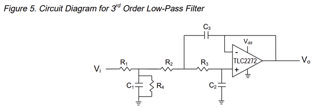
2) Please recommend an IC chip that we can use to convert the APWM signal to analog signal?
Thank you!