This thread has been locked.

If you have a related question, please click the "Ask a related question" button in the top right corner. The newly created question will be automatically linked to this question.

AM2432: Failure to Synchronize SYNC0 with PWM

Part Number: AM2432
Other Parts Discussed in Thread: SYSCONFIG

Tool/software:

Hi TI Experts,

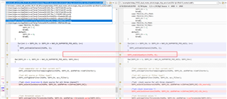
Customer is working on SDK9.1. Customer is running Ethercat on ICSSG0 and their Sigmadelta on ICSSG1.

They have followed the below thread to configure the SYNC0.

https://e2e.ti.com/support/microcontrollers/arm-based-microcontrollers-group/arm-based-microcontrollers/f/arm-based-microcontrollers-forum/1433438/am2434-change-ethercat-pru-sync0-pin?

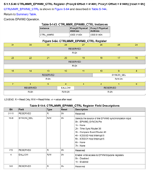
Their sysconfig configuration is shown below.

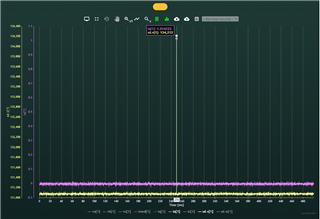
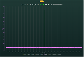
However, customer found that it will Failure to synchronize SYNC0 with PWM resulted in drift between SYNC0 and internal interrupts, along with sigma-delta current sampling noise and stalling.

Customer hopes to know if you could provide some guidance here.

Thanks,

Kevin

  • Hi Kevin,

    Is the mapping EtherCAT SYNC0 to PWM SYNCin done correctly?

    Also recommended to use the latest Industrial Communications SDK (version 09.02.00.24) as we have made some fixes with respect to the EtherCAT on ICSSG0 example initialisation of the MDIO Firmware and few improvements.

    Regards,
    Aaron

  • Hi Thomas,

    we did some sync mapping according to the reference. But I didn't see the synchronization among PWM, sync0 and internal task aligned to PWM. I suspect there is something we missed and hope you can review with us.

    Second issue is that we wonder how ti realize the clock synchronization in DC mode. Can you give us a brief introduction on ti solution of clock synchronization between network references clock and drive local clock based on timestamp in ECAT message, and tasks synchronization between ECAT sync0 and other tasks, like PWM, sigma delta current sensing, slower scheduler? It seems you have such solution from reference manual. Thanks a lot.

  • this is configuration in code

  • Hi Logan,

    Could you please also check this register value when running your code, thanks!

    Kevin

  • both are 0. don't understand why

  • Hi Logan

    Could you give a log printing both before and after you writing this register? So that we could know if you actually have write this register or not.

    Thanks,

    Kevin


  • we didn't write this line, I guess this is the reason. Meanwhile I am not sure if the follwing code is needed


    /* Force SW sync for EPWM0. Other PWMs will be sync'd through HW sync daisy-chain. */
    EPWM_tbTriggerSwSync(gEpwm0BaseAddr);

  • Hi Aaron,

    Based on the last reply from Logan, the previous value of CLTRMMR EPWM0 is always 0, which means the configuration is invalid.

    Customer found the root cause why this happens, as Logan mentioned, they need to add the unlock function before writing to the MMR register, and now they could read out the value to be 0x200, which indicates that time sync router 38 is configured now.

    Customer will test the actual behavior tomorrow and get back.

    Meanwhile, could you please feedback the question from Logan if the following code line is must needed or not?

    /* Force SW sync for EPWM0. Other PWMs will be sync'd through HW sync daisy-chain. */
    EPWM_tbTriggerSwSync(gEpwm0BaseAddr);

    Thanks,

    Kevin

  • Hello,

    The value of the register was 0.
    We added the following lines:


    Now the value is 512:


    We will check tomorrow if we has any improvement due to this change.

    thanks,
    Sergei

  • Hi Kevin, there is big improvment after we managed to write register correctly. PWM and sync0 are synced after it. But we saw current feedback noise. I think it's some syncing issue with sigma delta current sensing, any suggestions on debugging? 

    Thanks

    Logan

  • Kevin, we noticed that there is a update in sdk 9.2 example that it provides an API for the sync between epwm and  SDFM. It's not existed in 9.1. Can you explain how the sync is realized in 9.1? thanks

  • Hi Logan,

    In  9.1, SDFM and ePWM0 synchronization is configured in the firmware.
    But , in  9.2, we moved it into the  SDFM driver to handle the configuration through APIs.

    This noise issue seems related to the SDFM parameters, especially the SDFM clock. Could you share the configured SDFM parameters? And sd clock source configuration ? 

    Thanks & Regards

    Achala ram 

  • Hi Ram,

    Thanks for your help. we also think it's related to SDF parameters and configuration. My coworker Ariel will update the SDFM configurations. Here are more update on the current sensing noise phenomenons. And hope these info can help you.

    • we experienced the current sensing noise only in one drive phases, defined as phase V in our board. 
    • It  happens both in ECAT drive and Pulse-direction input drive (without ecat). Maybe Ecat makes it easier to happen.
    • we know it is sensing noise because the spikes of recorded current in software can reach 2A when motor is at standstill state. our ia is calculated based on iv and iw.
    •   
    • such phenomenon seldom happens, but it does happen. when it happens, it can last for very long time till power cycle sometimes. We usually do power cycle to reproduce it. And spikes happens pretty randomly in time, doesn't found perod on it.

    Thanks

    Logan

  • Regarding the SD configuration:

    void SigmaDeltaManagerAM243x::SDLoadDefaultParams()
    {
    uint16_t i,j;
    PRUManagerAM243x* p_pru_manager = PRUManagerAM243x::GetSingleton();
    sPruInfo s_pru_basic_info = p_pru_manager->GetApplicationInfo(ePruFunctions::PRU_SigmaDelta);

    for(i = 0; i<MAX_NUM_OF_AXES; i++)
    {
    SigmaDeltaManagerAM243x::m_Map_SD_Axis_Data[i].sSdfm_Params.u16_LoadShare = 0; /*loadshare*/
    SigmaDeltaManagerAM243x::m_Map_SD_Axis_Data[i].sSdfm_Params.u16_Pru_Id = s_pru_basic_info.m_u16_PRU_Id; // 1
    SigmaDeltaManagerAM243x::m_Map_SD_Axis_Data[i].sSdfm_Params.u16_Slice_Id = s_pru_basic_info.m_u16_PRU_Slice_Id; //1
    SigmaDeltaManagerAM243x::m_Map_SD_Axis_Data[i].sSdfm_Params.u32_Pru_Clock = 300000000; /*PRU clock*/
    SigmaDeltaManagerAM243x::m_Map_SD_Axis_Data[i].sSdfm_Params.p_Iep_Clock[0] = 300000000; /*Value of IEP clock*/
    SigmaDeltaManagerAM243x::m_Map_SD_Axis_Data[i].sSdfm_Params.p_Iep_Clock[1] = 0;
    SigmaDeltaManagerAM243x::m_Map_SD_Axis_Data[i].sSdfm_Params.u32_Sd_Clock = 20000000; /*Value of SD clock (It should be exact equal to sd clock value)*/
    SigmaDeltaManagerAM243x::m_Map_SD_Axis_Data[i].sSdfm_Params.u16_Is_Double_Update = 1; /*enable double update*/
    SigmaDeltaManagerAM243x::m_Map_SD_Axis_Data[i].sSdfm_Params.f_First_Sample_Trigger_Time = 54.4;/*first sample trigger time*/
    SigmaDeltaManagerAM243x::m_Map_SD_Axis_Data[i].sSdfm_Params.f_Second_Sample_Trigger_Time = 54.4 + 62.5; /*second sample trigger time*/
    SigmaDeltaManagerAM243x::m_Map_SD_Axis_Data[i].sSdfm_Params.u32_Epwm_Out_Freq = m_f_PWM_freq;/*PWM output frequency*/

    for(j = 0; j<NUM_CH_SUPPORTED; j++)
    {
    SigmaDeltaManagerAM243x::m_Map_SD_Axis_Data[i].sSdfm_Params.p_sThreshold_Parms[j] = {3500,1000,0}; /*threshold parameters(High, low & reserevd)*/
    SigmaDeltaManagerAM243x::m_Map_SD_Axis_Data[i].sSdfm_Params.p_sClock_Parms[j] = {0,0};/*clock sourse & clock inversion for all channels*/
    SigmaDeltaManagerAM243x::m_Map_SD_Axis_Data[i].sSdfm_Params.p_u32_Zero_Cross_Threshold[j] = 1700;
    }

    for(j = 0; j<NUM_SD_CH; j++)
    {
    SigmaDeltaManagerAM243x::m_Map_SD_Axis_Data[i].sSdfm_Params.p_u16_Fast_Detect[j][0] = 4;
    SigmaDeltaManagerAM243x::m_Map_SD_Axis_Data[i].sSdfm_Params.p_u16_Fast_Detect[j][1] = 18;
    SigmaDeltaManagerAM243x::m_Map_SD_Axis_Data[i].sSdfm_Params.p_u16_Fast_Detect[j][2] = 2;
    }

    SigmaDeltaManagerAM243x::m_Map_SD_Axis_Data[i].sSdfm_Params.u16_Over_Current_Osr = 255;/*Over current osr: The effect count is OSR + 1*/
    SigmaDeltaManagerAM243x::m_Map_SD_Axis_Data[i].sSdfm_Params.u16_Normal_Current_Osr = 63; /*Normal current osr: The effect count is OSR + 1*/
    SigmaDeltaManagerAM243x::m_Map_SD_Axis_Data[i].sSdfm_Params.u16_En_Over_Current = 0; /*comparator enable*/
    SigmaDeltaManagerAM243x::m_Map_SD_Axis_Data[i].sSdfm_Params.u32_Sdfm_Samples_Addr = (uint32_t)&g_p_u32_Sdfm_SampleOutput;
    SigmaDeltaManagerAM243x::m_Map_SD_Axis_Data[i].sSdfm_Params.u16_En_Fast_Detect = 0;
    SigmaDeltaManagerAM243x::m_Map_SD_Axis_Data[i].sSdfm_Params.u16_En_Phase_Delay = 0;
    SigmaDeltaManagerAM243x::m_Map_SD_Axis_Data[i].sSdfm_Params.u16_En_Zero_Cross = 0;
    SigmaDeltaManagerAM243x::m_Map_SD_Axis_Data[i].sSdfm_Params.u16_En_Continuous_Mode = 0;

    SigmaDeltaManagerAM243x::m_Map_SD_Axis_Data[i].u32_Axis_Current_V = 0;
    SigmaDeltaManagerAM243x::m_Map_SD_Axis_Data[i].u32_Axis_Current_W = 0;
    SigmaDeltaManagerAM243x::m_Map_SD_Axis_Data[i].u32_Max_Filter_Output_OSR = 262144;//m_map_OSR_MaxValue_Output.at((SigmaDeltaManagerAM243x::m_Map_SD_Axis_Data[i].sSdfm_Params.u16_Normal_Current_Osr + 1));

    }
    return;
    }

    Please assumg 'i' (the index) is 0 and never bigger

  • sdfm.asm

    This is our SDFM .asm - Please note it was edited with the following code you sent us at the time: Firmware2 (1).asm

  • I would like to verify that our sample times matches the expected times (quite zone consideration)

  • Hi Logan/Ariel,

    SigmaDeltaManagerAM243x::m_Map_SD_Axis_Data[i].sSdfm_Params.u32_Epwm_Out_Freq = m_f_PWM_freq;/*PWM output frequency*/

    Please share the configured value of "m_f_PWM_freq" /*PWM output frequency*/

    we experienced the current sensing noise only in one drive phases, defined as phase V in our board. 

    Which SDFM channel are you using for phase V ? is there any difference between the V phase and other (working phases) in terms of hardware settings or the SDFM clock input source?

    And what is the SDFM clock source? Are you using the ECAP provided in the SDK, or any external clock source?

    BR, 

    Achala Ram

  • m_f_PWM_freq = 8000 - please also assume a casting is performed and it's getting the correct value.

    channel 1 is used for phase V

    channel 2 is used for phase W

    channel 0 is configured - but not used ( .asm did not modify channel 0).

    SDFM is indeed as the sdk example - the ECAP provided

    SDFM_PRU = 1

    SDFM_TZ = 9

    Not really sure what you mean by: '? is there any difference between the V phase and other (working phases) in terms of hardware settings or the SDFM clock input source?'

    if the GPIO config does not answer your question: please elaborate

  • Hi Ariel,

    SDFM parameters and firmware changes look correct. I also tested the firmware you shared by configuring the same parameters but did not observe any noise on any channel.

    Not really sure what you mean by: '? is there any difference between the V phase and other (working phases) in terms of hardware settings or the SDFM clock input source?'

    Is there anything on the hardware side that could add noise to the CH1 SD data input? How are Channel 1 (SD1_DATA) and Channel 2 (SD2_DATA) receiving input? Are they receiving input from the same modulator or different modulators?

    Thanks & regarding,

    Achala Ram

  • I would also like to ask of you to review the following:

    /*below configuration for all three channel*/
    for(u16_sdfm_ch_num = 0; u16_sdfm_ch_num < NUM_CH_SUPPORTED_PER_AXIS; u16_sdfm_ch_num++)
    {

    /*set comparator osr or Over current osr*/
    SDFM_setCompFilterOverSamplingRatio(hSdfm, u16_sdfm_ch_num, p_sdfm_prms->u16_Over_Current_Osr);

    /*set ACC source or filter type*/
    SDFM_configDataFilter(hSdfm, u16_sdfm_ch_num, u16_accumolator_filter_type);

    /*set clock inversion & clock source for all three channel*/
    SDFM_selectClockSource(hSdfm, u16_sdfm_ch_num, p_sdfm_prms->p_sClock_Parms[u16_sdfm_ch_num]);

    /*set threshold values */
    SDFM_setCompFilterThresholds(hSdfm, u16_sdfm_ch_num, p_sdfm_prms->p_sThreshold_Parms[u16_sdfm_ch_num]);
    if(p_sdfm_prms->u16_En_Fast_Detect)
    {
    /*Fast detect configuration */
    SDFM_configFastDetect(hSdfm, u16_sdfm_ch_num, (uint8_t*)p_sdfm_prms->p_u16_Fast_Detect[u16_sdfm_ch_num]);
    }
    if(p_sdfm_prms->u16_En_Over_Current)
    {
    SDFM_enableComparator(hSdfm, u16_sdfm_ch_num);
    }
    else
    {
    SDFM_disableComparator(hSdfm, u16_sdfm_ch_num);
    }

    /*enabling Zero cross only for first channel of axis*/

    if(p_sdfm_prms->u16_En_Zero_Cross && ((p_sdfm_prms->u16_LoadShare && u16_sdfm_ch_num == 2)||(!p_sdfm_prms->u16_LoadShare)))
    {
    SDFM_enableZeroCrossDetection(hSdfm, u16_sdfm_ch_num, p_sdfm_prms->p_u32_Zero_Cross_Threshold[u16_sdfm_ch_num]);
    }

    }

    As I mentioned before - we are using channel 1 & 2 - however ch0 is still configured and the PRU code does sample it as well - though we do not use this data at all.

    Is there something here that might cause us problem if I configure ch0?

    Thanks

  • As I mentioned before - we are using channel 1 & 2 - however ch0 is still configured and the PRU code does sample it as well - though we do not use this data at all.

    Is there something here that might cause us problem if I configure ch0?

    No, it will not cause any problem with other channels (In firmware side). 

    we know it is sensing noise because the spikes of recorded current in software can reach 2A when motor is at standstill state. our ia is calculated based on iv and iw.

    Can you share the raw data of CH1 (values of g_p_u32_Sdfm_SampleOutput for 100-200 samples)? Is there any change of adding extra/random values when ia is being calculated?

    uch phenomenon seldom happens, but it does happen. when it happens, it can last for very long time till power cycle sometimes. We usually do power cycle to reproduce it. And spikes happens pretty randomly in time, doesn't found perod on it.

    Can you elaborate on this? is noise not observed sometimes after power reset for ch1(phase V)?

    Thanks & regards,

    Achala Ram

  • The method for ia calculation is not relevant - we can see a clear change in the raw reading of the channel (v).

    sd.v = channel 1/phase latch

    The ePWM is 50%.

    We are not using controller - only serial so there is no sync0 that effects the Duty Cycle.

    Again - I would like you to confirm our sampling time (first & second trigger).

    • such phenomenon seldom happens, but it does happen. when it happens, it can last for very long time till power cycle sometimes. We usually do power cycle to reproduce it. And spikes happens pretty randomly in time, doesn't found perod on it.

    No, this phenomenon rarely happens. It takes me several ten times of power cycle, about one hour, to capture one abnormal recording.

  • SigmaDeltaManagerAM243x::m_Map_SD_Axis_Data[i].sSdfm_Params.u16_Is_Double_Update = 1; /*enable double update*/
    SigmaDeltaManagerAM243x::m_Map_SD_Axis_Data[i].sSdfm_Params.f_First_Sample_Trigger_Time = 54.4;/*first sample trigger time*/
    SigmaDeltaManagerAM243x::m_Map_SD_Axis_Data[i].sSdfm_Params.f_Second_Sample_Trigger_Time = 54.4 + 62.5; /*second sample trigger

    Can you disable the double update and check, or trigger the second sample 2-3 µs earlier? The timing window of the third sample in the double update can mismatch if Sync0 occurs early or late (by 1-2 IEP count).

    The configured second sample trigger time is 116.9 µs, and the double update completion time is 9.6 µs, making the endpoint of the double update is126.5 µs (> 125us crossing IEP reset window). This can cause a problem if the IEP gets reset early or late by even one IEP count

    Thanks & Regards,

    Achala Ram 

  • Hi Ram

    https://e2e.ti.com/support/microcontrollers/arm-based-microcontrollers-group/arm-based-microcontrollers/f/arm-based-microcontrollers-forum/1327675/mcu-plus-sdk-am243x-sigma-delta-jitter-noise-when-adjusting-iep-reset-timer

    If you can recall - you already helped me solve this issue here - unless there are still missing parts needed to be done.

    We are using suggestion #2 (Firmware2.asm) - clear buffers each first NC sample.

    At the time - we saw it on both channel (v&w). We also shared it with you via video call.

    After the fix we didn't encounter it anymore - it was very much persistent and easy to reproduce.

    We already know the second sample time is after a new EPWM cycle starts.

    Even if the suggested FW does not solve this - how come we see the noise on only 1 channel and not both of them?

    Since the issue is very hard to reproduce (sometimes a few hours), I want to be 100% sure of any change we do and to understand the root cause of this issue.

    We must have the double sample enabled.

    Moving the second sample trigger a bit earlier is fine - but to my understanding I will miss the sample in the quite zone.

    So:

    1. I would like to have an answer if possible - what should be the most effective start sampling times for our first & second samples?

    2..Alternately - if solution #2 does reset the buffers there is no need for the IEP counter to do so. Is there a way to disable the auto reset of the SD buffers by the IEP counter?

    3. In addition - how does reversing the SD clock effects the FW?

    4. Is there any delay compensation between the channels? If so how does it work?