This thread has been locked.

If you have a related question, please click the "Ask a related question" button in the top right corner. The newly created question will be automatically linked to this question.

MSPM0G3507: Linker file Configuration of .text region

Part Number: MSPM0G3507
Other Parts Discussed in Thread: SYSCONFIG

Tool/software:

Hi team,

My customer is thinking to set a specific region for their application code.

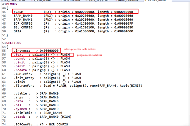
Let's say they want to place their code starting from 0x0000001 to 0x00008000 flash region,

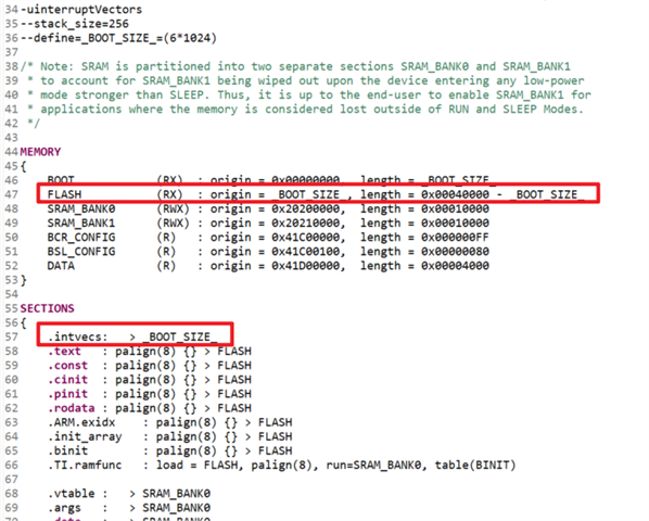
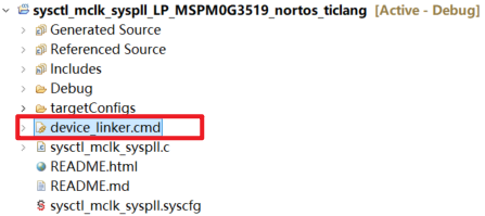
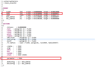
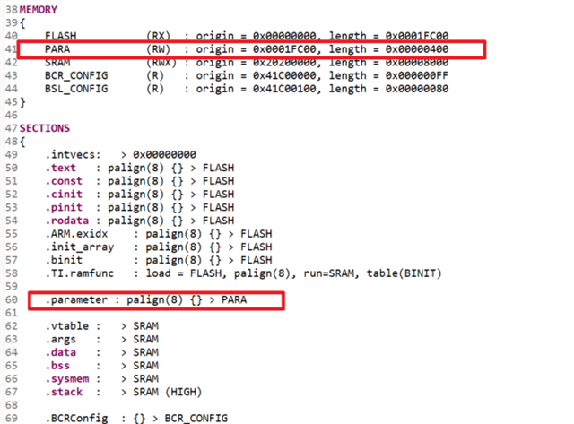
how should they change the code in sections of device_linker.cmd?

 Default: .text   : palign(8) {} > FLASH

Best regards,

Kenley

  • Hi Kenley,

    Sorry for late reply. Let me clarify for some cmd configuration rules about MSPM0:

    1. MSPM0 will always start from 0x0000 address after POR. So there should always be a boot program placed at 0x0000 address.

    2. Generally, we will try to make the application image start address aligned with 1 flash sector (1024Byte). So the start address 0x0000001 is not acceptable in this case.

    3. For example, if customer want to place the application code from 0x1800, the cmd could be such as: the FLASH region start address and the .intvecs address should be set as the desired start address. And another boot program should be placed at 0x0000 address to jump to application program. 

    Best Regards,

    Pengfei

  • Hi Pengfei,

    Thank you for your support.

    Is the following acceptable too ?

    'define _BOOTSIZE (0x0000_1800)
    
    MEMORY
    {
     BOOT    (RX)  : origin = 0x00000000, length = _BOOTSIZE
        FLASH           (RX)  : origin =_BOOTSIZE, length = 0x00020000 - _BOOTSIZE
        SRAM            (RWX) : origin = 0x20200000, length = 0x00008000
        BCR_CONFIG      (R)   : origin = 0x41C00000, length = 0x00000080
        BSL_CONFIG      (R)   : origin = 0x41C00100, length = 0x00000080
    }
    
    SECTIONS
    {
        .intvecs:   > _BOOTSIZE
        .text   : palign(8) {} > FLASH
        .const  : palign(8) {} > FLASH
        .cinit  : palign(8) {} > FLASH
        .pinit  : palign(8) {} > FLASH
        .rodata : palign(8) {} > FLASH
        .ARM.exidx    : palign(8) {} > FLASH
        .init_array   : palign(8) {} > FLASH
        .binit        : palign(8) {} > FLASH
        .TI.ramfunc   : load = FLASH, palign(8), run=SRAM, table(BINIT)
    
        .vtable :   > SRAM
        .args   :   > SRAM
        .data   :   > SRAM
        .bss    :   > SRAM
        .sysmem :   > SRAM
        .stack  :   > SRAM (HIGH)
    
        .BCRConfig  : {} > BCR_CONFIG
        .BSLConfig  : {} > BSL_CONFIG
    }
    

    Best regards,

    Kenley

  • Hi Kenley,

    Sure, it looks good. You have correct flash size and sram size for MSPM0G3507 device.

    Best Regards,

    Pengfei

  • Hi Pengfei,

    Customer did as you guide by modifying the device_linker.cmd but when they build it , the modified part is going back to default one.

    Could you help us on how can customer modify the file without going back to default when they build the project ?

    Best regards,

    Kenley

  • Hi Kenley,

    It is because the cmd file is default generated by SysConfig. You could follow below steps to modify the cmd file:

    1. Build the project, and the cmd file will be generated under Debug folder.

    2. Move the cmd file from the Debug folder to the current project folder, such as below:

    3. Open sysconfig file, and disable the cmd generation function such as below, and then customer could modify the cmd file and it will not be generated by sysconfig again.

    Best Regards,

    Pengfei

  • Hi Pengfei,

    Customer did as you told and wrote the firmware on the mcu but the program does not work.

    However, when resetting them to default, the program works.

    Could you look at their linker file ?

    /*****************************************************************************
    
      Copyright (C) 2023 Texas Instruments Incorporated - http://www.ti.com/ 
    
      Redistribution and use in source and binary forms, with or without
      modification, are permitted provided that the following conditions
      are met:
    
       Redistributions of source code must retain the above copyright
       notice, this list of conditions and the following disclaimer.
    
       Redistributions in binary form must reproduce the above copyright
       notice, this list of conditions and the following disclaimer in the
       documentation and/or other materials provided with the
       distribution.
    
       Neither the name of Texas Instruments Incorporated nor the names of
       its contributors may be used to endorse or promote products derived
       from this software without specific prior written permission.
    
      THIS SOFTWARE IS PROVIDED BY THE COPYRIGHT HOLDERS AND CONTRIBUTORS
      "AS IS" AND ANY EXPRESS OR IMPLIED WARRANTIES, INCLUDING, BUT NOT
      LIMITED TO, THE IMPLIED WARRANTIES OF MERCHANTABILITY AND FITNESS FOR
      A PARTICULAR PURPOSE ARE DISCLAIMED. IN NO EVENT SHALL THE COPYRIGHT
      OWNER OR CONTRIBUTORS BE LIABLE FOR ANY DIRECT, INDIRECT, INCIDENTAL,
      SPECIAL, EXEMPLARY, OR CONSEQUENTIAL DAMAGES (INCLUDING, BUT NOT
      LIMITED TO, PROCUREMENT OF SUBSTITUTE GOODS OR SERVICES; LOSS OF USE,
      DATA, OR PROFITS; OR BUSINESS INTERRUPTION) HOWEVER CAUSED AND ON ANY
      THEORY OF LIABILITY, WHETHER IN CONTRACT, STRICT LIABILITY, OR TORT
      (INCLUDING NEGLIGENCE OR OTHERWISE) ARISING IN ANY WAY OUT OF THE USE
      OF THIS SOFTWARE, EVEN IF ADVISED OF THE POSSIBILITY OF SUCH DAMAGE.
    
    *****************************************************************************/
    -uinterruptVectors
    --stack_size=512
    --define=_BOOTSIZE=(0x00008000)
    
    MEMORY
    {
        BOOT            (RX)  : origin = 0x00000000, length = _BOOTSIZE
        FLASH           (RX)  : origin = _BOOTSIZE, length = 0x00020000 - _BOOTSIZE
        SRAM            (RWX) : origin = 0x20200000, length = 0x00008000
        BCR_CONFIG      (R)   : origin = 0x41C00000, length = 0x00000080
        BSL_CONFIG      (R)   : origin = 0x41C00100, length = 0x00000080
    }
    
    SECTIONS
    {
        .intvecs:   > _BOOTSIZE
        .text   : palign(8) {} > FLASH
        .const  : palign(8) {} > FLASH
        .cinit  : palign(8) {} > FLASH
        .pinit  : palign(8) {} > FLASH
        .rodata : palign(8) {} > FLASH
        .ARM.exidx    : palign(8) {} > FLASH
        .init_array   : palign(8) {} > FLASH
        .binit        : palign(8) {} > FLASH
        .TI.ramfunc   : load = FLASH, palign(8), run=SRAM, table(BINIT)
    
        .vtable :   > SRAM
        .args   :   > SRAM
        .data   :   > SRAM
        .bss    :   > SRAM
        .sysmem :   > SRAM
        .stack  :   > SRAM (HIGH)
    
        .BCRConfig  : {} > BCR_CONFIG
        .BSLConfig  : {} > BSL_CONFIG
    }
    

    https://e2e.ti.com/cfs-file/__key/communityserver-discussions-components-files/908/spi_5F00_peripheral_5F00_echo_5F00_interrupts_5F00_LP_5F00_MSPM0G3507_5F00_nortos_5F00_ticlang.map

    Thank you in advance,

    Kenley

  • Hi Kenley,

    Do you mean they download this project start with 0x8000 address and directly run the program?

    Actually our MSPM0 will always start with 0x0000 address after power-on, so it is necessary to push a boot project at 0x0000 address and jump to the application project at 0x8000 in the boot project.

    Attach a simple slide about how to achieve program jumping from boot program to application program.

    Program Jump Guide.pptx

    Best Regards,

    Pengfei

  • Sure, it looks good. You have correct flash size and sram size for MSPM0G3507 device.

    Hi Pengfei, previously you said that their code was no problem. Do you mean they need to change the linker file again and follow the instructions on the program jump guide ?

    Regards,

    Kenley

  • Hi Pengfei,

    Thanks to you now customer can run the program normally. 

    Customer would like to add user parameter settings and create flash image for that.

    For example adding the parameter file between vector table and the program code or create a new image file by combining the parameter file after the first program image (.out, txt file, etc.) generated by the build.

    Do you have any recommendation what is the best solution for customer?

    Thank you,

    Kenley

  • Hi Kenley,

    Sorry what do you mean of "parameter setting file"?

    If customer want to define the address for the vector table and program code for different application images, they could modify .cmd linker file to achieve this. 

    Best Regards,

    Pengfei

  • Hi Pengfei,

    Sorry for my unclear explanation.

    For example customer would like to add .parameter in the section between .intvecs and .text. 

    What should customer do ?

    For example: 

    1. Edit the .cmd file as above such as: 

    .parameter : palign(8) {} > FLASH 

    2. Create a new source file .c in CCS project ?
    __attribute__((section(".parameter")))

    const uint_8t parameter[256] = {0x12, 0x34, .... };

    3. Add the following in the main.c file.

    extern const uint8_t parameter [256];

    Best regards,

    Kenley

  • Hi Pengfei

    For your reference, seems like there is similar thread 
    MSPM0G3507: Linker Command File - Arm-based microcontrollers forum - Arm-based microcontrollers - TI E2E support forums

    But it is not explaining how to modify the "SECTIONS" by adding userconfig memory in the "MEMORY".

    Regards,

    Kenley

  • Hi Kenley,

    Does customer want to store these .parameter section data into FLASH or SRAM?

    Generally the code will be stored in .text section in FLASH, and the variables in program will be stored in SRAM (.data, .bss, .stack). 

    From your description, I think customer want to assign a section in SRAM to store some particular parameters.  

    They could define the .parameter sector such as below:

    And as you said, they could then use __attribute__((section(".parameter"))) in their source code to define variables in .parameter sector. 

    Best Regards,

    Pengfei

  • Hi Pengfei,

    Thank you for your support.

    They want to store these parameter section data into flash so the parameter data will always be there even the power is off.

    In this case, how should customer do it ?

    Regards,

    Kenley

  • Hi Kenley,

    Customer could follow below guide for store data to a point address.:

    1. Define the cmd linker file as below, this is mainly for reserve a flash region which will not be used for code.

    2. In source file, define the parameters at a pointed address location, and the initial value will be loaded when program downloaded.

    Best Regards,

    Pengfei

  • Hi Pengfei,

    Thank you for your support.

    A quick confirmation. 

    So if customer want to change the value of the parameter, customer can change the value in the __attribute uint32_t paraData{64} = {0}; to uint32_t paraData{64} = {0,1,2,3,4,...};.

    Is my understanding correct ?

    Regards,

    Kenley

  • Hi Kenley,

    Yes, correct.