This thread has been locked.

If you have a related question, please click the "Ask a related question" button in the top right corner. The newly created question will be automatically linked to this question.

TM4C129XNCZAD: How to set up interrupt for transmit buffer empty

Part Number: TM4C129XNCZAD

Tool/software:

Our device has RS485 communication enabled and it's working okay, but I want to switch to be only interrupt driven communication so the processor doesn't have to sit and loop while waiting for characters to be transmitted.

This is the code to enable one of the serial ports:

ROM_IntEnable(INT_UART1);
ROM_UARTIntEnable(UART1_BASE, UART_INT_RX | UART_INT_RT);

Do I need to add UART_INT_TX, as below?

ROM_UARTIntEnable(UART1_BASE, UART_INT_RX | UART_INT_RT | UART_INT_TX);

I found this command in sample code:

MAP_UARTFIFOLevelSet(g_ui32Base, UART_FIFO_TX1_8, UART_FIFO_RX1_8);

Does that mean an interrupt will be generated when there is one character left in the transmit buffer?

Is that what I use to trigger an interrupt telling me it's time to put more characters in the transmit buffer?

Here are the first lines in our interrupt handler:

UARTHB_Status = ROM_UARTIntStatus(UART1_BASE, true); // Get the interrrupt status
ROM_UARTIntClear(UART1_BASE, UARTHB_Status); // Clear the asserted interrupts

Do these statements clear all interrupts, or will I need to add something else to clear a transmit interrupt?

This is the code I'm using to fill the output buffer.  Feel free to comment.

for( i = 0 ; i < 300; i++) // Fill FIFO buffer. NOTE: The FIFO buffer was never enabled until v2.27.
{
if(must_resend_char_HB)
global_char_HB = character_to_resend_HB;
else
global_char_HB = get_from_output_buffer_HB();
if ( UARTCharPutNonBlocking(UartPort_HB, global_char_HB) == false ) // character did not go in FIFO, must try again. UART1_BASE
{
must_resend_char_HB = true;
character_to_resend_HB = global_char_HB;
break;
}
else
{
must_resend_char_HB = false;
}

if(out_wrptr_HB == out_rdptr_HB)
{
Host_1_HB_transmission_finished = true;
characters_to_send_HB = false;
break;
}

}

Thanks very much.

  • Do I need to add UART_INT_TX, as below?

    ROM_UARTIntEnable(UART1_BASE, UART_INT_RX | UART_INT_RT | UART_INT_TX);

    You can add UART_INT_TX to first prepare data in the TXFIFO. However, it is not absolutely necessary. You could also wait for the the RX interrupt to arrive and in the RX ISR, write your data to the TXFIFO.   I will suggest you try out both to see which one best suits your application. 

    I found this command in sample code:

    MAP_UARTFIFOLevelSet(g_ui32Base, UART_FIFO_TX1_8, UART_FIFO_RX1_8);

    Does that mean an interrupt will be generated when there is one character left in the transmit buffer?

    There are 16 entries in both the TX and RX FIFO.  Therefore, for FIFO_TX1_8 and FIFO_RX1_8 means the interrupt is generated when 2 entries are left in the FIFO. 

    Is that what I use to trigger an interrupt telling me it's time to put more characters in the transmit buffer?

    That is correct. When 2 entries as in FIFO_TX1_8 are left in the TXFIFO, it will interrupt the application to put more data into the FIFO. 

    Here are the first lines in our interrupt handler:

    UARTHB_Status = ROM_UARTIntStatus(UART1_BASE, true); // Get the interrrupt status
    ROM_UARTIntClear(UART1_BASE, UARTHB_Status); // Clear the asserted interrupts

    Do these statements clear all interrupts, or will I need to add something else to clear a transmit interrupt?

    This is the code I'm using to fill the output buffer.  Feel free to comment.

    Yes, your code will clear flags that are set as recorded in UARTHB_Status.

    This is the code I'm using to fill the output buffer.  Feel free to comment.

    for( i = 0 ; i < 300; i++) // Fill FIFO buffer. NOTE: The FIFO buffer was never enabled until v2.27.
    {
    if(must_resend_char_HB)
    global_char_HB = character_to_resend_HB;
    else
    global_char_HB = get_from_output_buffer_HB();
    if ( UARTCharPutNonBlocking(UartPort_HB, global_char_HB) == false ) // character did not go in FIFO, must try again. UART1_BASE
    {
    must_resend_char_HB = true;
    character_to_resend_HB = global_char_HB;
    break;
    }
    else
    {
    must_resend_char_HB = false;
    }

    if(out_wrptr_HB == out_rdptr_HB)
    {
    Host_1_HB_transmission_finished = true;
    characters_to_send_HB = false;
    break;
    }

    }

    Don't really see a problem. 

  • Thank you very much, I have it working now... for the most part. First a question:

    Can you explain more the following? "You can add UART_INT_TX to first prepare data in the TXFIFO."

    Now, continuing with my device working most of the time.  Occasionally I have a watchdog reset, so I think there is an interrupt occurring that I'm not handling.  Any idea what it might be?  I'll try to include all relevant code here.

    First, the transmit interrupt is enabled.

    ROM_UARTIntEnable(UART1_BASE, UART_INT_RX | UART_INT_RT | UART_INT_TX); // Adding UART_INT_TX here to enable transmit interrupts

    Configuration:

    ROM_UARTConfigSetExpClk(UART1_BASE, ui32SysClock, 9600, (UART_CONFIG_WLEN_8 | UART_CONFIG_STOP_ONE | UART_CONFIG_PAR_ODD)); // Odd parity required per our Modbus spec

    In the interrupt handler:

    UARTHB_Status = ROM_UARTIntStatus(UART1_BASE, true); // This returns a bit mapped value of all the interrupts that are active so they can be cleared.
    ROM_UARTIntClear(UART1_BASE, UARTHB_Status); // Clear all the interrupts that were active in the previous read. (Check the documentation for UARTIntEnable to see the bits.)

    if(UARTHB_Status & (UART_INT_RX | UART_INT_RT))
    {
    while(ROM_UARTCharsAvail(UART1_BASE))
    {
    ch = UARTCharGetNonBlocking(UART1_BASE); // What would happen if there were no character available?
    put_in_input_buffer_HB( (char)ch );
    HB_Time_Out = 0; // Reset if we got a character
    }
    hm1flag = true; // This flag starts the process to determine when a new message is available to process
    }

    To turn off the RS485 transmitter:

    I have code in a separate half millisecond interrupt to come back later and turn off the transmitter.  I see there is an option to get an interrupt when the last bit is sent.  I think I need to implement that.

    if (Host_1_HB_transmission_finished) // Turn off RS485 transmitter when it's time to do so
    {
    if(UARTBusy(UartPort_HB) == false) // When UARTBusy becomes false, we're done transmitting, continue to disable transmitter
    {
    Disable_UartPort_HB_Transmiter(); // Moved here to the interrupt in v2.27
    Host_1_HB_transmission_finished = false; // Transmitter has now been turned off, reset flag
    transmit_active_HB = false; // All done transmitting
    }
    }

    Am I missing anything?

  • Can you explain more the following? "You can add UART_INT_TX to first prepare data in the TXFIFO."

    For example, after UART is set up the first time, the TXFIFO will be empty. If you enable for TX interrupt with a 1/8 threshold, the TX interrupt will fire immediately since empty is less than 1/8 of the FIFO. In the ISR for TXFIFO interrupt, you can write a maximum of 16 data into the TX FIFO. The next TX interrupt will not come until there are only two data left in the TXFIFO which is when 14 data has been sent.

    Now, continuing with my device working most of the time.  Occasionally I have a watchdog reset, so I think there is an interrupt occurring that I'm not handling.  Any idea what it might be?  I'll try to include all relevant code here.

    Watchdog will first generate an NMI interrupt before it will pull reset. You need to check if you have cleared the WD interrupt. 

    If the timer counts down to its zero state again before the first time-out interrupt is cleared, and the
    reset signal has been enabled by setting the RESEN bit in the WDTCTL register, the Watchdog timer
    asserts its reset signal to the system. If the interrupt is cleared before the 32-bit counter reaches its
    second time-out, the 32-bit counter is loaded with the value in the WDTLOAD register, and counting
    resumes from that value.

    First, the transmit interrupt is enabled.

    ROM_UARTIntEnable(UART1_BASE, UART_INT_RX | UART_INT_RT | UART_INT_TX); // Adding UART_INT_TX here to enable transmit interrupts

    Configuration:

    ROM_UARTConfigSetExpClk(UART1_BASE, ui32SysClock, 9600, (UART_CONFIG_WLEN_8 | UART_CONFIG_STOP_ONE | UART_CONFIG_PAR_ODD)); // Odd parity required per our Modbus spec

    I don't see a problem so far. 

    In the interrupt handler:

    UARTHB_Status = ROM_UARTIntStatus(UART1_BASE, true); // This returns a bit mapped value of all the interrupts that are active so they can be cleared.
    ROM_UARTIntClear(UART1_BASE, UARTHB_Status); // Clear all the interrupts that were active in the previous read. (Check the documentation for UARTIntEnable to see the bits.)

    if(UARTHB_Status & (UART_INT_RX | UART_INT_RT))
    {
    while(ROM_UARTCharsAvail(UART1_BASE))
    {
    ch = UARTCharGetNonBlocking(UART1_BASE); // What would happen if there were no character available?
    put_in_input_buffer_HB( (char)ch );
    HB_Time_Out = 0; // Reset if we got a character
    }
    hm1flag = true; // This flag starts the process to determine when a new message is available to process
    }

    The TX and RX interrupts are shared by the same ISR. Where is your code to handle TX interrupt? If a TX interrupt comes, you simply clear the flag, isn't?

    Your code here is basically what I said earlier that you don't really need to enable TXFIFO interrupt. When a RX interrupt comes, you can just write data to the TXFIFO to start a transmission based on what is receive. 

    In the uart_echo example, it has the similar code. 

    void
    UARTIntHandler(void)
    {
        uint32_t ui32Status;
    
        //
        // Get the interrrupt status.
        //
        ui32Status = MAP_UARTIntStatus(UART0_BASE, true);
    
        //
        // Clear the asserted interrupts.
        //
        MAP_UARTIntClear(UART0_BASE, ui32Status);
    
        //
        // Loop while there are characters in the receive FIFO.
        //
        while(MAP_UARTCharsAvail(UART0_BASE))
        {
            //
            // Read the next character from the UART and write it back to the UART.
            //
            MAP_UARTCharPutNonBlocking(UART0_BASE,
                                       MAP_UARTCharGetNonBlocking(UART0_BASE));
    
            //
            // Blink the LED to show a character transfer is occuring.
            //
            MAP_GPIOPinWrite(GPIO_PORTN_BASE, GPIO_PIN_0, GPIO_PIN_0);
    
            //
            // Delay for 1 millisecond.  Each SysCtlDelay is about 3 clocks.
            //
            SysCtlDelay(g_ui32SysClock / (1000 * 3));
    
            //
            // Turn off the LED
            //
            MAP_GPIOPinWrite(GPIO_PORTN_BASE, GPIO_PIN_0, 0);
        }
    }

  • My mistake.  I shared code in the interrupt handler to receive, but not to transmit.  Here it is:

    if(UARTHB_Status & (UART_INT_TX))
    {
    if(characters_to_send_HB)
    {
    for( i = 0; i < 300; i++) // Fill FIFO buffer. NOTE: The FIFO buffer was never enabled until v2.27.
    {
    if(must_resend_char_HB)
    global_char_HB = character_to_resend_HB;
    else
    global_char_HB = get_from_output_buffer_HB();
    if ( UARTCharPutNonBlocking(UartPort_HB, global_char_HB) == false ) // character did not go in FIFO, must try again. UART1_BASE (replaces UARTCharPut)
    {
    character_to_resend_HB = global_char_HB;
    must_resend_char_HB = true;
    break;
    }
    else
    {
    must_resend_char_HB = false;
    }

    //while(UARTBusy(UartPort_HB)); // We definitely will not be looping here like this while we send out over the UART, especially in an interrupt!

    if(out_wrptr_HB == out_rdptr_HB)
    {
    Host_1_HB_transmission_finished = true;
    characters_to_send_HB = false;
    break;
    }

    }
    }
    }

    The main object of this exercise is to avoid looping in the main code, waiting until the transmit register is empty to turn off the RS485 transmitter.

    I still don't understand this: "Your code here is basically what I said earlier that you don't really need to enable TXFIFO interrupt. When a RX interrupt comes, you can just write data to the TXFIFO to start a transmission based on what is receive."

    My problem is not starting the transmission, my problem is knowing when to turn off the transmitter, and I don't want to sit and loop.

    I will have a look at the watchdog settings.  My code is working and can work for an hour, I think, without a reset.  Am I not handling a certain condition that might also cause an interrupt and keep me locked in the interrupt?

    Thanks.

  • I still don't understand this: "Your code here is basically what I said earlier that you don't really need to enable TXFIFO interrupt. When a RX interrupt comes, you can just write data to the TXFIFO to start a transmission based on what is receive."

    Sorry for the confusion. I guess you can disregard my above comment as it may not be suitable for your application. I was referring to the uart_echo example code for the RX interrupt handling (see below again). In this interrupt ISR, when to call UARTCharPutNonBlocking to fill the TXFIFO depends on what is received. 

    MAP_UARTCharPutNonBlocking(UART0_BASE, MAP_UARTCharGetNonBlocking(UART0_BASE));

    void
    UARTIntHandler(void)
    {
        uint32_t ui32Status;
    
        //
        // Get the interrrupt status.
        //
        ui32Status = MAP_UARTIntStatus(UART0_BASE, true);
    
        //
        // Clear the asserted interrupts.
        //
        MAP_UARTIntClear(UART0_BASE, ui32Status);
    
        //
        // Loop while there are characters in the receive FIFO.
        //
        while(MAP_UARTCharsAvail(UART0_BASE))
        {
            //
            // Read the next character from the UART and write it back to the UART.
            //
            MAP_UARTCharPutNonBlocking(UART0_BASE,
                                       MAP_UARTCharGetNonBlocking(UART0_BASE));
    
            //
            // Blink the LED to show a character transfer is occuring.
            //
            MAP_GPIOPinWrite(GPIO_PORTN_BASE, GPIO_PIN_0, GPIO_PIN_0);
    
            //
            // Delay for 1 millisecond.  Each SysCtlDelay is about 3 clocks.
            //
            SysCtlDelay(g_ui32SysClock / (1000 * 3));
    
            //
            // Turn off the LED
            //
            MAP_GPIOPinWrite(GPIO_PORTN_BASE, GPIO_PIN_0, 0);
        }
    }

    My problem is not starting the transmission, my problem is knowing when to turn off the transmitter, and I don't want to sit and loop.

    Don't you know how many you are expecting to receive? If you know ahead of time how many to receive then you can turn off the transmitter how receiving the expected count of data. Or you could turn off the transmitter after certain duration of inactivity on the bus using a timer. 

  • We are mainly doing Modbus communication, so the host computer could send a Function 1, 2, 3, 4, 6 (or some others, also) type message, defined according to our implementation of the Modbus protocol.  There is a required silent period of the equivalent of 3.5 characters and then if the message received was a valid query or command, our device could respond.  I think it would be very hard or impossible to know in advance how many characters will be received, but we can look for that timeout after characters stop coming.

    Once a reply is composed, we can turn on the RS485 transmitter.  Once all characters are sent, I have a another check in a half millisecond periodic interrupt to see when transmission is done and leave a little delay and then turn off the transmitter.  There should be a delay before the host sends another query or command.

    It's now working with all transmitting being handled in the interrupt (instead of just sitting and looping in the main loop, waiting for transmission to finish to turn off the transmitter), but once in a while the system stops communicating and then our device does a reset after maybe 7 to 10 seconds.  A communication error should not cause a reset like this.

    I'm used to our system running for hours without any communication errors here in the office.  Please let me know if you have any ideas on where to start looking for why it would reset.  One thought is that if an interrupt is happening that I'm not aware of and I never clear the condition that is causing the interrupt, and if it keeps calling the interrupt handler, that would cause a watchdog reset.

  • How can I find out more about these items in the TivaWareTm Peripheral Driver Library?  How can I find out what causes a DSR interrupt?

    30.2.2.30 UARTIntEnable
    Enables individual UART interrupt sources.
    Prototype:
    void
    UARTIntEnable(uint32_t ui32Base,
    uint32_t ui32IntFlags)
    Parameters:
    ui32Base is the base address of the UART port.
    ui32IntFlags is the bit mask of the interrupt sources to be enabled.
    Description:
    This function enables the indicated UART interrupt sources. Only the sources that are enabled
    can be reflected to the processor interrupt; disabled sources have no effect on the processor.
    The ui32IntFlags parameter is the logical OR of any of the following:
    UART_INT_9BIT - 9-bit Address Match interrupt
    UART_INT_OE - Overrun Error interrupt
    UART_INT_BE - Break Error interrupt
    UART_INT_PE - Parity Error interrupt
    UART_INT_FE - Framing Error interrupt
    UART_INT_RT - Receive Timeout interrupt
    UART_INT_TX - Transmit interrupt
    UART_INT_RX - Receive interrupt
    UART_INT_DSR - DSR interrupt
    UART_INT_DCD - DCD interrupt
    UART_INT_CTS - CTS interrupt
    UART_INT_RI - RI interrupt
    Returns:
    None.

  • Hi Mark,

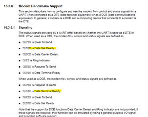
      If you are not using UART in modem or flow control mode then you should not be getting the DTR error. DSR is for Data Set Ready. Are you getting an DSR interrupt? 

      Also wanted to give you heads-up that I will be on vacation tomorrow until the end of the week. My response will be delayed. 

  • Thanks for the heads up on your schedule.  I am not getting that interrupt, I just pulled out one that I didn't immediately recognize.

    If I may ask, what document did you quote here?  Is that a TI document.

    Thanks

  • Yes, it is from the datasheet. Just search for DSR in the device datasheet.