This thread has been locked.

If you have a related question, please click the "Ask a related question" button in the top right corner. The newly created question will be automatically linked to this question.

AM263P4-Q1: How To Debug Missing Resolver Excitation Output?

Part Number: AM263P4-Q1
Other Parts Discussed in Thread: SYSCONFIG

Tool/software:

Hello,

I have custom HW on which I can run your example project: resolver_angle_speed_am263px-cc_r5fss0-0_nortos_ti-arm-clang from SDK 9.2.0.56.

I have to comment out the multiplexing since it's NA.

    //Board_driversOpen();
    /* setting up resolver related pins on board muxes */
    //i2c_io_expander_resolver_adc();

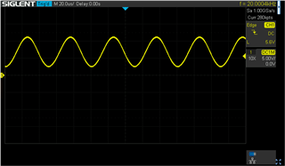
And also change the excitation output from D16 to D17 but that's it. Here's the excitation sine wave to my resolver with the example project:

And the example output:

[Cortex_R5_0] setting up the EPWM ISR!!
setting up the EPWM ISR Complete!!
Resolver Enabled!!
Forcing the Sync Pulse from the EPMW0!!
4000 Iterations complete. Printing some of the values
	    ANGLES (DEGREES)					||	VELOCITIES (RPS)			
----------------------------------------------------------------||-----------------------------------------------
	ATAN		RAW_TRACK2	SW_TRAKC2		||	HW_TRACK2		SW_TRACK2
	83.457642	83.364258	-0.006338		||	83.369751	83.391724
	83.446655	83.419189	83.397217		||	0.006747	0.006747
	83.474121	83.413696	83.391724		||	0.006165	0.006165
	83.430176	83.424683	83.402710		||	0.007423	0.007423
	83.430176	83.424683	83.402710		||	0.007232	0.007232
	83.402710	83.419189	83.397217		||	0.006859	0.006859
	83.430176	83.413696	83.391724		||	0.006487	0.006487
	83.446655	83.408203	83.386230		||	0.004764	0.004764
	83.446655	83.413696	83.391724		||	0.006319	0.006319
	83.457642	83.413696	83.391724		||	0.006370	0.006370
All tests have passed!!

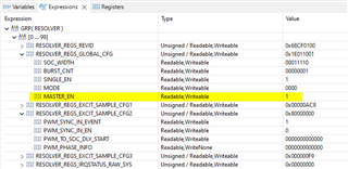
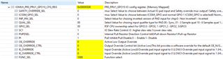
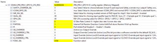
My problem is that when I carry over the same configurations (RESOLVER, EPWM, EPWM SYNCOUT XBAR) to our application project using the same custom HW, I do not see the excitation output. The cause must be software but I am struggling to understand how to find the root cause.

The contents of Drivers_epwmSyncoutXbarOpen(), Drivers_epwmOpen() and Drivers_resolverOpen() are identical between the example and my Application.

I am calling the following once in my application


RDC_enableResolver(CONFIG_RESOLVER0_BASE_ADDR);
EPWM_forceSyncPulse(RESOLVER_SYNC_BASE_ADDR);

But after this I don't see any PWM output.

I'd really appreciate some pointers to debug where it's going wrong please. For reference, PFA the modified example project that runs on my custom HW.

resolver_angle_speed_am263px-cc_r5fss0-0_nortos_ti-arm-clang.zip

Thank you.

  • Hi Kier,

    Apologies for the late reply. Few basic checks I can think of, considering the code being same between the hardware

    • Are you probing on the exact same pin (D16 or D17) in the new hardware? Can you cross verify this once with your schematic?
    • If probing on the right pin, can you please cross verify on the hardware once with respect to if any of the series resistors on the trace connecting D16 and D17 have been removed (unmounted or DNI)?
    • Can you just try a simple GPIO toggle on the same D16 and D17 pin and see if you can prove it being toggled, just to ensure the setup and probing to be right.

    I will also ask my colleague to look at it from a software perspective. In the meantime, can you please check for the above if possible?

    Thanks,

    Tejas Kulakarni

  • Hi Tejas,

    Thank you but your requests suggest an incorrect understanding of the the situation. This is not a matter of software working on one PCB but not another, different PCB. I have identical hardware in working and non working conditions.

    Few basic checks I can think of, considering the code being same between the hardware

    The code is not the same, only the parts (I think) are relevant to the resolver, TBC by TI.

    I've gone much further than basic checks as explained in the opening question which presents evidence as to why is unlikely to be a hardware problem. In short, when comparing the working and not working conditions:

    - The hardware is identical.

    - The contents of Drivers_epwmSyncoutXbarOpen(), Drivers_epwmOpen() and Drivers_resolverOpen() are identical.

    - The pin muxing for D17 is identical.

    What I need is list of register field values to check (or other suggestion) to try to understand why there is no PWM output in my application please.

  • Hi Kier,

    Apologies for the misunderstanding. I will ask my colleague to look at it from software perspective.

    I see that the difference in behaviour is between

    resolver_angle_speed_am263px-cc_r5fss0-0_nortos_ti-arm-clang from SDK 9.2.0.56

    and 

    resolver_angle_speed_am263px-cc_r5fss0-0_nortos_ti-arm-clang.zip

    Thanks,

    Tejas Kulakarni

  • Hi Tejas,

    That's not correct.

    The difference in behaviour is between:

    (1) resolver_angle_speed_am263px-cc_r5fss0-0_nortos_ti-arm-clang from SDK 9.2.0.56 but modified a little (OK)

    ...and...

    (2) my application (not OK)

    ...where both softwares are running on the same custom HW.

    I have attached (1) as a zip file (called resolver_angle_speed_am263px-cc_r5fss0-0_nortos_ti-arm-clang.zip) just for your reference because I had to modify it slightly from the example code.

    I am not allowed to give you (2) of course.

  • HI Kier,

    I handle the SW for Resolver. I am trying to understand the issue you are facing. There isn't really anything in the board configurations that should configure/limit the Resolver apart from the IO-Expanders which should not be applicable in your case of custom hardware.

    I see that pmic, i2c, mcspi are still on in the drivers-open. pmic open may be looking for some response from the on-board peripherals. I tried the following on your project, and see its running now.

    1. Board.c file, remove from build or comment it out
      1. resolver_angle_speed.c
      2. remove the extern definition of the i2c-io-expander
      3. //extern void i2c_io_expander_resolver_adc();
    2. syscfg file
      1. remove pmic and dependent modules added like MCSPI, I2C, EDMA if not used in the project

    Thanks and regards,

    Madhava

  • Hi Kier,

    Please find attached the below project file with changes that Madhava has mentioned above

    resolver_angle_speed_am263px-cc_r5fss0-0_nortos_ti-arm-clang-Madhava_modified.zip

    Please do write back if there are any further queries regarding this.

    Thanks,

    Tejas Kulakarni

  • Hi Madhava,

    I see that pmic, i2c, mcspi are still on in the drivers-open. pmic open may be looking for some response from the on-board peripherals. I tried the following on your project, and see its running now.

    Thank you but the zip file I attached is not my target project, it is TIs project from the SDK plus modifications. This project works fine on my HW already so does not need further modifications. It is just there for reference as a demonstration that I can get a PWM output on my HW.

    My project (which I cannot give to you) does not work. My request is that you advise me which registers to check in my project to see if there's anything not set correctly which might prevent PWM output.

    So for example, presumably RESOLVER_REGS_GLOBAL_CFG.MASTER_EN must be set to get a PWM output. Is that correct? Perhaps not, I don't know. The point is that I'd like you to tell me what registers to check to try to find the cause of no PWM output.

  • Hi Kier,

    Please check the Resolver registers,

    1. see if the master_en bit is set. in RESOLVER_REGS_GLOBAL_CFG bit 0
    2. see if you have the pwm sync en. in RESOLVER_REGS_EXCIT_SAMPLE_CFG2 bit 29
      1. if enbaled, then see sync_in_event status. in RESOLVER_REGS_EXCIT_SAMPLE_CFG2 bit 31
      2. if not, no need to check.

    From the reset defaults, these are the Resolver registers you'd need for the Resolver to generate a 10KHz Resolver PWM out. if your IOMUX is configured correctly, then the waveform should be available. 

    If needed, try compiling your applicaiion in Debug mode (reduces the optimization level and keeps static inline APIs as a callable functions) step through the resolver configuration APIs and see if resolver registers are updating correctly. 

    Apart from these, Attached zip file has everything right for the resolver to work. (with the comments I had earlier replied) if your actual project is already doing everything exactly same as this shared project, with respect to the resolver (and PWM sync and PWM Xbar configuration) configurations, there should not be any issue with the Resolver generating a PWM out signal. Tejas and I checked the PWM OUT signals on both D16 and D17.

    So I have a few follow up questions,

    1. Your application and the shared one, do they have Resolver configurations identical? 
    2. PWM sync and PWM Xbar, in your application are configured correctly (similar or identical to the shared one)
    3. IOMUX is configuring D16/D17 correctly? and the corresponding PIN is not shorted to anything else? 
      1. Please don't take me wrong we have encountered similar scenarios while designing the amplifier circuitries in very early stages of development. 
    4. If PWM sync is being used, is your EPWM counter running?  
      1. if not one or both of these could be possibilities, 
        1. TB Counter mode may be Stop and Freeze mode
        2. TBCLKSYNC is disabled
      2. if not, are you forcing the Sync signal like the application you shared?
    5. Are you seeing this issue with this particular board or few more similar boards?
      1. expecting some error scenario where pin "might" have gone bad. 
      2. try GPIO configuration and toggling for D16/D17 like Tejas suggested to confirm the PIN is good. I understand this is highly unlikely.

    Thanks and regards,

    Madhava 

  • Hi Kier,

    In addition to things mentioned by Madhava above, since you mentioned you cannot share your project, if it is fine, can you please share only the SysConfig part of your code? We would be able to check the Resolver and IOMUX configurations using that and would help with the debug a lot. Please do share that if fine.

    Thanks,
    Tejas Kulakarni

  • Thank you very much for the comprehensive debug points. I think these will be very useful.

    • see if the master_en bit is set. in RESOLVER_REGS_GLOBAL_CFG bit 0
    • see if you have the pwm sync en. in RESOLVER_REGS_EXCIT_SAMPLE_CFG2 bit 29
      1. if enbaled, then see sync_in_event status. in RESOLVER_REGS_EXCIT_SAMPLE_CFG2 bit 31
      2. if not, no need to check.

    Thank you. Here's the resolver registers:

    with respect to the resolver (and PWM sync and PWM Xbar configuration) configurations, there should not be any issue with the Resolver generating a PWM out signal.

    OK, thanks for the confirmation.

    IOMUX is configuring D16/D17 correctly?

    Bingo! This is the root cause. After Pinmux_config() is called, the pin function for D17 is correct (8):

    But then after running my code for a few seconds I rechecked and the pin function has changed to TRC_DATA2

    I remember now that my application is trying to use TRACE. So I disabled the TRACE feature and now I get excitation output with my application.

    Apologies, I should have checked this sooner rather than later. I guess this is the benefit of a second pair of eyes!

  • Hi Tejas,

    can you please share only the SysConfig part of your code?

    Thank you, that's a good idea. In future I will post my .syscfg.

    As you can see, the problem is solved now but thanks for your efforts to progress it.

  • Hi Kier,

    Thank you for letting us know. Please feel free to write back to us, if there is anything else.

    Regards,

    Tejas Kulakarni