This thread has been locked.

If you have a related question, please click the "Ask a related question" button in the top right corner. The newly created question will be automatically linked to this question.

AM2434: Invalid LPSC state transition for EMIF_CFG_0 Module (DDR Turn On)

Part Number: AM2434

Tool/software:

I've got a new product in the aerospace domain that's using the AM2434 chip (field-securable variant). Due to certification constraints, we've opted to disable the DMSC via performing the Secure Handover operation. As such, we now get to write our own drivers for system control functionality. I understand this is not TI's recommendation.

Currently I'm trying to enable the DDR interface for a custom SBL and am running into puzzling behavior. Following the TRM, AM243x SDK, and TI GEL files, I've been able to replicate the MPU, PLL, and PSC controllers to start enabling system hardware. The problem is the LPSC controller for the EMIF_CFG_0 module domain. I can enable all power/module domains in the chip EXCEPT that one. I can even enable the EMIF_DATA_0 module, despite the TRM claiming that I can't enable it until the EMIF_CFG_0 domain is enabled. 

I configure the settings for the power transition, issue the GO command, and get hung up waiting for GOSTAT to clear. To reiterate, this same driver works fine for all other module domains.I've enabled/configured all the PLLs in the system (except MCU) according to the TI GEL files (AM24_PLL_PARAMS_OFC1.gel), which I understand is a dependency of using the LPSC module correctly due to auto-clock gating functionality.

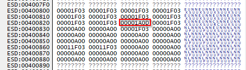
What I observe in the system MD_STAT register block is that all module domains I configure end up in a "good" state 0x1F03, but the EMIF_CFG_0 domain ends up at 0x1A0D, which doesn't appear to mean anything according to the listed enum values in the SDK.

What am I missing here? It feels incredibly odd that I can enable the EMIF_DATA_0 domain but not the CFG domain. By all appearances these two are linked together so meeting the "turn on" dependencies of one should enable the other.

  • I should mention this is occurring on the AM243x EVM board, not a custom pcb.

  • Hi Brandon,

    i would agree that is strange, not sure what is going on .  Ensure the you have the DDR PLL (PLL12) enabled and locked before you try to enabled the LPSCs for the DDR.  

    I assume you have translated the GEL scripts into some C code to run on the processor.  So are you booting with this custom SBL? Or somehow downloading binaries to the processor?  Just trying to understand the full environment from powering on the board to the failure.

    Maybe one test:  are you able to run the GELs after your code fails to configure EMIF_CFG_0?  Maybe there is something different in its execution which may give you a clue.

    Regards,

    James


  • I can confirm PLLCTRL0 and PLL12 is enabled and locked when I try to enable the DDR LPSC modules.


    Yes, I was using the GEL scripts, the SDK drivers, and two other company products utilizing the J7 and AM64x series chips as my references. Their LPCS drivers seemed extremely similar, if not identical. I saw the exact same 0x1A0D behavior when I tried to enable the LPSC_ADC domain without first enabling all the necessary clocks, however the PLL12 and MAIN_SYSCLK0 (via PLLCTRL0_PLLSTAT) dependencies are both locked. I'm pretty puzzled since the behavior implies I'm missing a PLL clock somewhere.

    I'm unable to run the GEL files after my code fails due to my development environment being entirely within VSCode + Trace32. I got my software into a while(1), detached T32, and switched over to CCS, however attaching seems to reset my board and destroy the configurations I had loaded.

    Is there an example project that directly configures DDR from DEV_BOOT mode? I was looking around for one to use with CCS, but I may have missed it.

    As far as my boot process goes, I've got a T32 script that places the chip into reset, then releases the DMSC to execute for a few seconds to initialize the device, halts the chip and loads my SBL directly into SRAM and continues execution from SRAM. The first thing I do is configure my MPU, then load the SYSFW (v11.0.0.15) and the EVM board default config hex header files (which succeeds), and then I proceed to perform the Secure Handover (also succeeds) and finally continue on to PLL then PSC configuration, at which point I run into the described error.

  • Hi Brandon,

    Are you connecting to the 20-pin cTI connector when you try to switch to CCS?  if so, the JTAG_EMU_RSTn signal might be causing this.  There are couple of things you can try to get around this:

    -physically remove the connection.  Not an easy mod to do this on the board from what i can see.  What i have done in the past is physically bend the pin on the JTAG connector out of the way so it doesn't make connection with the pod

    -you might be able to establish a connection with CCS before the error occurs, and after connecting to one of the cores, you can put it in Run->Free Run mode, then halt after the failure.  Not sure if any of that will conflict with your T32 connection.  

    Another option:

    On the Lauterbach website, there are cmm scripts that are essentially translated GEL scripts that will configure PSC/PLL and also the DDR

    https://repo.lauterbach.com/cgi-bin/searchscript.pl?form=scripts&Terms=am243&searchresult=Searching+&fper=on&fmen=on&fhardware=on&fkernel=on&fcompiler=on&fflash=on&fmisc=on#hardware-arm~am24xx~am24x-skevm~scripts

    With these, you shouldn't need to switch pods for CCS, and then you can run the PSC scripts to see if you can redo the PSC init to see if it works with the script.

    You may also try just executing up to the secure handover point, and then from there try the cmm scripts to init the PLL and PSC, and see if you get different behavior.

    Regards,

    James 

  • You may also try just executing up to the secure handover point, and then from there try the cmm scripts to init the PLL and PSC, and see if you get different behavior.

    That was incredibly helpful. I've found my issue by comparing against the Lauterbach scripts, which as you would expect, configure the HW correctly.

    The problem was that I followed the TRM PLL configuration instructions, or I've misunderstood the intent. Table 5-994 lists this statement:


    So naturally, I have a check in my software that counts the number of set bits in HSDIV_PRSNC in the CFG register. PLL12 lists only 1 divider.


    This also matches up with the block diagram of the PLLs:


    The fix? CLK_POSTDIV_EN must always be enabled irrespective of the HSDIV_PRSNC count. Not sure why this is the case, but the TRM needs updating to not include that instruction. Reading the description for that bit shows if 0, all synchronous divided clocks are held low, HOWEVER, Table 5-987 claims this shouldn't affect the HSDIV because its clock is sourced from FOUTP, which is not gated by CLK_POSTDIV_EN.


    This is confusing, because just one page further, you get this diagram, showing that HSDIV[0-4] is actually sourced by FOUTPOSTDIV.


    I understand now where I went wrong, but I really feel the TRM could improve by removing/clarifying the instruction to disable CLK_POSTDIV_EN.