Part Number: MSPM0G1507
Other Parts Discussed in Thread: LP-MSPM0G3507, , MSPM0G3507
Tool/software:
Hi TI Community,
I am facing an issue during board bring-up and would appreciate your insights.
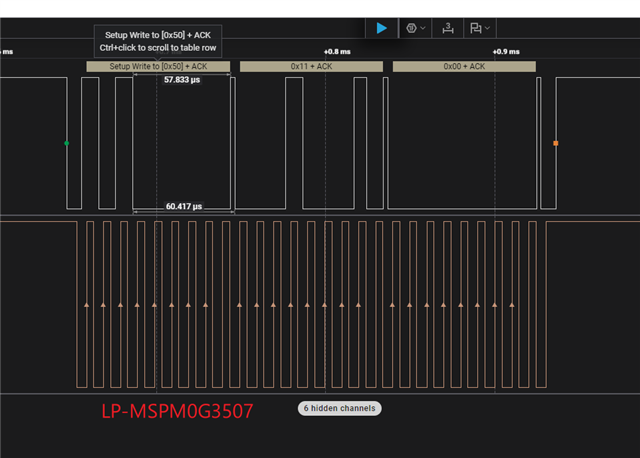
I successfully developed and tested an I2C firmware on the LP-MSPM0G3507 LaunchPad1. The I2C communication (using I2C0: PA0 as SDA, PA1 as SCL) works correctly, writing to two different ICs without any issues.
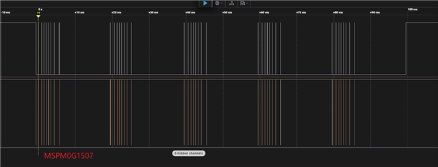
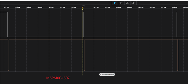
However, when I flash the exact same firmware onto a custom board featuring the MSPM0G1507 microcontroller, the I2C communication fails to work entirely.
To help diagnose the problem, I’ve confirmed the following:
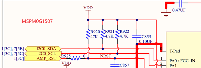
Hardware Connections: The SDA and SCL lines are properly connected with appropriate pull-up resistors (e.g., 4.7kΩ for 400kHz communication as a reference, though I'm running at a lower speed).
Pin Multiplexing: The firmware uses the same pin assignments (PA0 for SDA, PA1 for SCL).
Software Configuration: The I2C driver configuration (e.g., speed, interrupt settings) is identical to what worked on the G3507.
My specific questions are:
Are there any known differences in the I2C module or GPIO peripheral between the MSPM0G3507 and MSPM0G1507 that could cause the same firmware to fail on the latter?
Could there be a silicon revision or errata related to the I2C module on the MSPM0G1507 that I should be aware of?
What are the key areas I should investigate when porting I2C code from one MSPM0 family device to another, even if they appear similar in the datasheet?
Are there any specific register settings or clock configurations (e.g., related to the I2C peripheral clock source) that might differ between these two devices and need explicit re-initialization?
Any suggestions on how to debug this further would be greatly appreciated. I am using Code Composer Studio (CCS) and have access to a logic analyzer for signal inspection.
Thank you for your time and support.
Best regards,
Pakho