This thread has been locked.

If you have a related question, please click the "Ask a related question" button in the top right corner. The newly created question will be automatically linked to this question.

LM4F232 CAN0 not working on Port N and Port F

Hi,

I am using CAN0 on the EK-LM4F232, and it works fine when I use PB4 and PB5.  However, if I use PN0 and PN1 and PF0 and PF3,  CAN0 doesn't seem to function.  I have also checked the registers, and they are all set correctly.  The following is the pin configuration for CAN0 and CAN0 configuration, does anyone know what I am missing? 

================ Port B ================
ROM_SysCtlPeripheralEnable(SYSCTL_PERIPH_GPIOB);
ROM_GPIOPinConfigure(GPIO_PB4_CAN0RX);
ROM_GPIOPinConfigure(GPIO_PB5_CAN0TX);
ROM_GPIOPinTypeCAN(GPIO_PORTB_BASE, GPIO_PIN_4 | GPIO_PIN_5);

================ Port N ================
ROM_SysCtlPeripheralEnable(SYSCTL_PERIPH_GPION);
ROM_GPIOPinConfigure(GPIO_PN0_CAN0RX);
ROM_GPIOPinConfigure(GPIO_PN1_CAN0TX);
ROM_GPIOPinTypeCAN(GPIO_PORTN_BASE, GPIO_PIN_0 | GPIO_PIN_1);

================ CAN 0 Config. ================
ROM_SysCtlPeripheralEnable(SYSCTL_PERIPH_CAN0);
ROM_CANInit(CAN0_BASE);
ROM_CANBitRateSet(CAN0_BASE, 16000000, 1000000);
ROM_IntEnable(INT_CAN0);
ROM_CANIntEnable(CAN0_BASE, CAN_INT_MASTER | CAN_INT_ERROR | CAN_INT_STATUS);
ROM_CANEnable(CAN0_BASE); 
CANConfigureNetwork();

Thank you

regards,

Kevin

  • Kevin,

    If you assign a single signal to more than one pin location, it will only appear on the port with the lowest letter.  You'll have to remove it from Port B before you assign it to port F or port N.

    Regards,

    Sue

  • Hi Sue,

    I do have only one pin location.  I just merely posted all my pin configuration for comparison here.    My pin configuration for Port N is same as Port B, but CAN0 only works when I assign it to Port B.  However, when I assign it to Port N or Port F, CAN0 doesn't work.  Can you tell what is wrong with my Port N configuration for CAN0?

    Thank you

    Kevin

  • Hi Kevin,

    There is a recently discovered erratum that the PCTL for pin F0 defaults to 0x3, which is CAN0Rx.  Try changing that value before you assign it to Port N and see if that helps.

    Regards,

    Sue

  • Hi Sue,

    I just tried to set PF0 to a GPIO and assigned CAN0 to Port N, but CAN0 is still not working.  The following is my Port F GPIO configuration.  Am I configuring it wrong?


     ROM_SysCtlPeripheralEnable(SYSCTL_PERIPH_GPIOF);

     HWREG(GPIO_PORTF_BASE + GPIO_O_LOCK) = GPIO_LOCK_KEY_DD;
     HWREG(GPIO_PORTF_BASE + GPIO_O_CR) = GPIO_PIN_0;
     HWREG(GPIO_PORTF_BASE + GPIO_O_AFSEL) &= 0xfe;
     HWREG(GPIO_PORTF_BASE + GPIO_O_PCTL) = 0x00;
     HWREG(GPIO_PORTF_BASE + GPIO_O_LOCK) = GPIO_LOCK_KEY_DD;
     HWREG(GPIO_PORTF_BASE + GPIO_O_CR) = 0x00;
     HWREG(GPIO_PORTF_BASE + GPIO_O_LOCK) = GPIO_LOCK_M;

    By the way, I have also tried to assign CAN0 to Port F, but it is not working either.  PF0 is assigned to CAN0RX by default, so I thought I could just assign CAN0Rx to PF0 and CAN0Tx to PF3, and it would just work, but it's not.  Is there workaround in order for me to use CAN0 on Port F?

    Thank you

    regards,

    Kevin

  • Hi Kevin,

    I'm not sure what the issue is.  Your code seems fine.  When you say it doesn't work, how are you determining that it doesn't work?  Are you stepping through the code to see what happens?  Are you perhaps changing the initialization in another section of code?  We have verified with a LM4F232 board here that CAN0 operates correctly on Port B, Port F and Port N.

    Regards,

    Sue

  • Hi Sue,

    I have a CAN bus analyzer to receive the data sent from the LM4f232.  When I use Port B, the analyzer can receive data from LM4f232 correctly.  However, when I use Port F or Port N, the analyzer doesn't receive anything.  Also, I have CANH and CANL signals on a scope, and I don't see anything on CANH or CANL.  I am also stepping through the code to make sure if the registers are set correctly, and they all seem fine. 

    Regards,

    Kevin

  • Hi Kevin,

    I'm sorry for the delay in responding. Where are you with this issue?  Have you tried more than one part?  I think you should send the part back to us for analysis.  We know it works if it is configured correctly and your part appears to be correctly configured.

    Regards,

    Sue

  • Thanks for your posting.  I was trying to get the EKS-LM4F232 CAN working on PB3,4.  I was missing a couple of lines of code (and a few air gaps on my bread board).

    I have Tx coming out of the board now and have scoped out the Rx line on PB4 and know I am getting what looks like a great CAN signal.

    But my interrupt is not hitting and the registers for the CAN controller are not changing.

    I have not configured anything else on PortB.  I am working off of the simple_rx and simple_tx examples.

    Would you have any ideas why messages are on the bus to receive but no Rx messages are seen by the CAN controller?

  • I may have solved my own problem. 

    While scoping out the TX/Rx lines, I reset the EKS - probably from shorting 3V to ground.  The EKS seemed to reset just fine, with the downloaded program functioning and starting a new debug session (after CCS aborts) - however, I curiously lost the console to my 115,200 terminal.  I did not think much of that, but when I noticed that the CAN controller registers were reacting quite predictably to the TX and RX of message, but the ISR was never called, I finally put two and two together and removed power from the EKS.  Once again my terminal is working and the interrupt is getting called - all with no code changes.  So I guess the lesson may be to cycle power to the EKS when your pin fiddling causes a reset.

  • Hi John,

    Thanks for posting your resolution.  I was just sitting down to look at your question, so I appreciate you saving me time!

    Regards,

    Sue

  • Hi Sue,

    Actually, I have just tried another EK-LM4f232, and CAN0 works on Port F and Port N.  However, with the very same code, CAN0 doesn't work on Port F on my first EK-LM4f232; CAN0 on Port N works fine.  I have noticed the markings on these two ICs are different.  The Marking on the IC that CAN0 doesn't work on Port F is 18AH5VW when the working one is 19AD23W.  I have also contacted my local TI FAE, but his IC, whose marking is also 18AH5VW, so I think it could be something else wrong with my first EVM.  Anyway,  I am just going to use my second EK-LM4f232.  Thank you so much for your help.

    Regards,

    Kevin

  • Hi Kevin,

    Thanks for the update.  The first part is very early silicon, so it is possible the test program wasn't robust enough to catch the CAN0 problem.  I'm sorry you spent so much time on it, but I'm glad that you are moving forward with the second board.

    Regards,

    Sue

  • Hi,

    My EK-LM4F232 is 19AD23W, CAN0 works on port B.

    But, CAN0 doesn't work on Port F,too.

    Does TI find out the root cause ?

    Best regards,

    Simen

  • Simen,

    Did changing the port B assignments to something other than CAN0 fix the problem?

    Regards,

    Sue

  • I dropped the effort.  After laying out our prototype board we went with PortB for independent reasons. 

    However, .... I was just hacking around trying to get PF0 to be output.  This is the same pin used for CAN0Rx.  I had to disable the NMI function on this pin before I could.  Perhaps that is the problem with PF0 used as CAN0Rx.

    Good luck

  • Hi John,

    Yes, PF0 and PD7 are both under GPIO commit control and the GPIOLOCK register must be used to change their functionality - similar to the JTAG pins on Port C.

    Regards,

    Sue

  • Thanks,everyone.

    This issue has been solved.

    The lastest errata mentions it.

    The workround code as below:

        //================ CAN0 on Port F ================
        SysCtlPeripheralEnable(SYSCTL_PERIPH_GPIOF);        //enable PortF
        HWREG(GPIO_PORTF_BASE + GPIO_O_LOCK) = GPIO_LOCK_KEY_DD;
        HWREG(GPIO_PORTF_BASE + GPIO_O_CR) |= GPIO_PIN_0;
        HWREG(GPIO_PORTF_BASE + GPIO_O_AFSEL) |= ~0x80;
        GPIOPinTypeGPIOInput(GPIO_PORTF_BASE, GPIO_PIN_0);
        HWREG(GPIO_PORTF_BASE + GPIO_O_LOCK) = GPIO_LOCK_KEY_DD;
        HWREG(GPIO_PORTF_BASE + GPIO_O_CR) &= ~0x80;
        HWREG(GPIO_PORTF_BASE + GPIO_O_LOCK) = 0;

        GPIOPinConfigure(GPIO_PF0_CAN0RX);        //PF0->CAN0Rx ,PF3->CAN0Tx
        GPIOPinConfigure(GPIO_PF3_CAN0TX);
        GPIOPinTypeCAN(GPIO_PORTF_BASE,  GPIO_PIN_0|GPIO_PIN_3);        //PF0->CAN0Rx ,PF3->CAN0Tx


  • LPH said:

    Hi,

    I am also using EK-LM4F232,and I would like to know how do i calculate input parameter for

    GPIOPinConfigure(parameter)

    #Define GPIO_PB4_CAN0RX  ???

    #define GPIO_PB5_CAN0TX   ???


    one of example program gives

    #define GPIO_PD0_CAN0RX  0x00030002

    #define GPIO_PD0_CAN0TX  0x00030402

    i am tying to understand how it is calculated ?

    ROM_GPIOPinConfigure(GPIO_PB4_CAN0RX);
    ROM_GPIOPinConfigure(GPIO_PB5_CAN0TX);
    ================ Port N ================
    ROM_GPIOPinConfigure(GPIO_PN0_CAN0RX);
    ROM_GPIOPinConfigure(GPIO_PN1_CAN0TX);
    ================ CAN 0 Config. ================

  • Satheesh Ramasamy said:

    Hi,

    I am also using EK-LM4F232,and I would like to know how do i calculate input parameter for

    GPIOPinConfigure(parameter)

    #Define GPIO_PB4_CAN0RX  ???

    #define GPIO_PB5_CAN0TX   ???


    one of example program gives

    #define GPIO_PD0_CAN0RX  0x00030002

    #define GPIO_PD0_CAN0TX  0x00030402

    i am tying to understand how it is calculated ?

    ROM_GPIOPinConfigure(GPIO_PB4_CAN0RX);
    ROM_GPIOPinConfigure(GPIO_PB5_CAN0TX);
    ================ Port N ================
    ROM_GPIOPinConfigure(GPIO_PN0_CAN0RX);
    ROM_GPIOPinConfigure(GPIO_PN1_CAN0TX);
    ================ CAN 0 Config. ================

    [/quote]

    Satheesh,

    They are defined in pin_map.h, and they peripheral base address.

    BTW, you can't use the same GPIO for both CAN0 TX and RX.  Also, CAN0 is not one of alternative functions of PD0.  CAN0Rx is only available on PF0, PN0, PB4, or PE4 as CAN0Tx on PF3, PN1, PB5, or PE5.  so if you deicde to use Port F, you simply need to use GPIO_PF0_CAN0RX for CAN0Rx and GPIO_PF1_CAN0TX for CAN0Tx

    Hope this helps.

    Kevin


  • int main(void) { tCANMsgObject sCANMessage; unsigned char ucMsgData[4]; // // Set the clocking to run directly from the external crystal/oscillator. // TODO: The SYSCTL_XTAL_ value must be changed to match the value of the // crystal on your board. // SysCtlClockSet(SYSCTL_SYSDIV_1 | SYSCTL_USE_OSC | SYSCTL_OSC_MAIN | SYSCTL_XTAL_16MHZ); // // Set up the serial console to use for displaying messages. This is // just for this example program and is not needed for CAN operation. // InitConsole(); // // For this example CAN0 is used with RX and TX pins on port D0 and D1. // The actual port and pins used may be different on your part, consult // the data sheet for more information. // GPIO port D needs to be enabled so these pins can be used. // TODO: change this to whichever GPIO port you are using // SysCtlPeripheralEnable(SYSCTL_PERIPH_GPIOB); // // Configure the GPIO pin muxing to select CAN0 functions for these pins. // This step selects which alternate function is available for these pins. // This is necessary if your part supports GPIO pin function muxing. // Consult the data sheet to see which functions are allocated per pin. // TODO: change this to select the port/pin you are using // GPIOPinConfigure(GPIO_PB4_CAN0RX); GPIOPinConfigure(GPIO_PB5_CAN0TX); // // Enable the alternate function on the GPIO pins. The above step selects // which alternate function is available. This step actually enables the // alternate function instead of GPIO for these pins. // TODO: change this to match the port/pin you are using // GPIOPinTypeCAN(GPIO_PORTB_BASE, GPIO_PIN_4 | GPIO_PIN_5); // // The GPIO port and pins have been set up for CAN. The CAN peripheral // must be enabled. // SysCtlPeripheralEnable(SYSCTL_PERIPH_CAN0); // // Initialize the CAN controller // CANInit(CAN0_BASE); // // Set up the bit rate for the CAN bus. This function sets up the CAN // bus timing for a nominal configuration. You can achieve more control // over the CAN bus timing by using the function CANBitTimingSet() instead // of this one, if needed. // In this example, the CAN bus is set to 500 kHz. In the function below, // the call to SysCtlClockGet() is used to determine the clock rate that // is used for clocking the CAN peripheral. This can be replaced with a // fixed value if you know the value of the system clock, saving the extra // function call. For some parts, the CAN peripheral is clocked by a fixed // 8 MHz regardless of the system clock in which case the call to // SysCtlClockGet() should be replaced with 8000000. Consult the data // sheet for more information about CAN peripheral clocking. // CANBitRateSet(CAN0_BASE, SysCtlClockGet(), 500000); // // Enable interrupts on the CAN peripheral. This example uses static // allocation of interrupt handlers which means the name of the handler // is in the vector table of startup code. If you want to use dynamic // allocation of the vector table, then you must also call CANIntRegister() // here. // // CANIntRegister(CAN0_BASE, CANIntHandler); // if using dynamic vectors // CANIntEnable(CAN0_BASE, CAN_INT_MASTER | CAN_INT_ERROR | CAN_INT_STATUS); // // Enable the CAN interrupt on the processor (NVIC). // IntEnable(INT_CAN0); // // Enable the CAN for operation. // CANEnable(CAN0_BASE); // // Initialize the message object that will be used for sending CAN // messages. The message will be 4 bytes that will contain an incrementing // value. Initially it will be set to 0. // *(unsigned long *)ucMsgData = 0; sCANMessage.ulMsgID = 0x500; // CAN message ID - use 1 sCANMessage.ulMsgIDMask = 0; // no mask needed for TX sCANMessage.ulFlags = MSG_OBJ_TX_INT_ENABLE; // enable interrupt on TX sCANMessage.ulMsgLen = sizeof(ucMsgData); // size of message is 4 sCANMessage.pucMsgData = ucMsgData; // ptr to message content // // Enter loop to send messages. A new message will be sent once per // second. The 4 bytes of message content will be treated as an unsigned // long and incremented by one each time. // for(;;) { // // Print a message to the console showing the message count and the // contents of the message being sent. // UARTprintf("Sending msg: 0x%02X %02X %02X %02X", ucMsgData[0], ucMsgData[1], ucMsgData[2], ucMsgData[3]); // // Send the CAN message using object number 1 (not the same thing as // CAN ID, which is also 1 in this example). This function will cause // the message to be transmitted right away. // CANMessageSet(CAN0_BASE, 1, &sCANMessage, MSG_OBJ_TYPE_TX); // // Now wait 1 second before continuing // SimpleDelay(); // // Check the error flag to see if errors occurred // if(g_bErrFlag) { UARTprintf(" error - cable connected?\n"); } else { // // If no errors then print the count of message sent // UARTprintf(" total count = %u\n", g_ulMsgCount); } // // Increment the value in the message data. // // (*(unsigned long *)ucMsgData)++; (*(unsigned long *)ucMsgData)= (*(unsigned long *)ucMsgData)+10; } // // Return no errors // return(0);

    With the above code i am not able to see tx output in oscilloscope. Rx is connected with 3.3V

    Any idea why i am not able to see the wave form in osicilloscope?

  • the code you pasted here is not easy to read, as it is not organized. I would advice you to just make a new post.

  • void CANIntHandler(void) {

    void
    CANIntHandler(void)
    {
        unsigned long ulStatus;

        //
        // Read the CAN interrupt status to find the cause of the interrupt
        //
        ulStatus = CANIntStatus(CAN0_BASE, CAN_INT_STS_CAUSE);

        //
        // If the cause is a controller status interrupt, then get the status
        //
        if(ulStatus == CAN_INT_INTID_STATUS)
        {
            //
            // Read the controller status.  This will return a field of status
            // error bits that can indicate various errors.  Error processing
            // is not done in this example for simplicity.  Refer to the
            // API documentation for details about the error status bits.
            // The act of reading this status will clear the interrupt.  If the
            // CAN peripheral is not connected to a CAN bus with other CAN devices
            // present, then errors will occur and will be indicated in the
            // controller status.
            //
            ulStatus = CANStatusGet(CAN0_BASE, CAN_STS_CONTROL);

            //
            // Set a flag to indicate some errors may have occurred.
            //
            g_bErrFlag = 1;
        }

        //
        // Check if the cause is message object 1, which what we are using for
        // sending messages.
        //
        else if(ulStatus == 1)
        {
            //
            // Getting to this point means that the TX interrupt occurred on
            // message object 1, and the message TX is complete.  Clear the
            // message object interrupt.
            //
            CANIntClear(CAN0_BASE, 1);

            //
            // Increment a counter to keep track of how many messages have been
            // sent.  In a real application this could be used to set flags to
            // indicate when a message is sent.
            //
            g_ulMsgCount++;

            //
            // Since the message was sent, clear any error flags.
            //
            g_bErrFlag = 0;
        }

        //
        // Otherwise, something unexpected caused the interrupt.  This should
        // never happen.
        //
        else
        {
            //
            // Spurious interrupt handling can go here.
            //
        }
    }


    int
    main(void)
    {
        tCANMsgObject sCANMessage;
        unsigned char ucMsgData[4];

        //
        // Set the clocking to run directly from the external crystal/oscillator.
        // TODO: The SYSCTL_XTAL_ value must be changed to match the value of the
        // crystal on your board.
        //
        SysCtlClockSet(SYSCTL_SYSDIV_1 | SYSCTL_USE_OSC | SYSCTL_OSC_MAIN |
                       SYSCTL_XTAL_16MHZ);

        //
        // Set up the serial console to use for displaying messages.  This is
        // just for this example program and is not needed for CAN operation.
        //
        InitConsole();

        //
        // For this example CAN0 is used with RX and TX pins on port D0 and D1.
        // The actual port and pins used may be different on your part, consult
        // the data sheet for more information.
        // GPIO port D needs to be enabled so these pins can be used.
        // TODO: change this to whichever GPIO port you are using
        //
        SysCtlPeripheralEnable(SYSCTL_PERIPH_GPIOB);

        //
        // Configure the GPIO pin muxing to select CAN0 functions for these pins.
        // This step selects which alternate function is available for these pins.
        // This is necessary if your part supports GPIO pin function muxing.
        // Consult the data sheet to see which functions are allocated per pin.
        // TODO: change this to select the port/pin you are using
        //
        GPIOPinConfigure(GPIO_PB4_CAN0RX);
        GPIOPinConfigure(GPIO_PB5_CAN0TX);

        //
        // Enable the alternate function on the GPIO pins.  The above step selects
        // which alternate function is available.  This step actually enables the
        // alternate function instead of GPIO for these pins.
        // TODO: change this to match the port/pin you are using
        //
        GPIOPinTypeCAN(GPIO_PORTB_BASE, GPIO_PIN_4 | GPIO_PIN_5);

        //
        // The GPIO port and pins have been set up for CAN.  The CAN peripheral
        // must be enabled.
        //
        SysCtlPeripheralEnable(SYSCTL_PERIPH_CAN0);

        //
        // Initialize the CAN controller
        //
        CANInit(CAN0_BASE);

        //
        // Set up the bit rate for the CAN bus.  This function sets up the CAN
        // bus timing for a nominal configuration.  You can achieve more control
        // over the CAN bus timing by using the function CANBitTimingSet() instead
        // of this one, if needed.
        // In this example, the CAN bus is set to 500 kHz.  In the function below,
        // the call to SysCtlClockGet() is used to determine the clock rate that
        // is used for clocking the CAN peripheral.  This can be replaced with a
        // fixed value if you know the value of the system clock, saving the extra
        // function call.  For some parts, the CAN peripheral is clocked by a fixed
        // 8 MHz regardless of the system clock in which case the call to
        // SysCtlClockGet() should be replaced with 8000000.  Consult the data
        // sheet for more information about CAN peripheral clocking.
        //
        CANBitRateSet(CAN0_BASE, SysCtlClockGet(), 500000);

        //
        // Enable interrupts on the CAN peripheral.  This example uses static
        // allocation of interrupt handlers which means the name of the handler
        // is in the vector table of startup code.  If you want to use dynamic
        // allocation of the vector table, then you must also call CANIntRegister()
        // here.
        //
        // CANIntRegister(CAN0_BASE, CANIntHandler); // if using dynamic vectors
        //
        CANIntEnable(CAN0_BASE, CAN_INT_MASTER | CAN_INT_ERROR | CAN_INT_STATUS);

        //
        // Enable the CAN interrupt on the processor (NVIC).
        //
        IntEnable(INT_CAN0);

        //
        // Enable the CAN for operation.
        //
        CANEnable(CAN0_BASE);

        //
        // Initialize the message object that will be used for sending CAN
        // messages.  The message will be 4 bytes that will contain an incrementing
        // value.  Initially it will be set to 0.
        //
        *(unsigned long *)ucMsgData = 0;
        sCANMessage.ulMsgID = 0x500;                        // CAN message ID - use 1
        sCANMessage.ulMsgIDMask = 0;                    // no mask needed for TX
        sCANMessage.ulFlags = MSG_OBJ_TX_INT_ENABLE;    // enable interrupt on TX
        sCANMessage.ulMsgLen = sizeof(ucMsgData);       // size of message is 4
        sCANMessage.pucMsgData = ucMsgData;             // ptr to message content

        //
        // Enter loop to send messages.  A new message will be sent once per
        // second.  The 4 bytes of message content will be treated as an unsigned
        // long and incremented by one each time.
        //
        for(;;)
        {
            //
            // Print a message to the console showing the message count and the
            // contents of the message being sent.
            //
            UARTprintf("Sending msg: 0x%02X %02X %02X %02X",
                       ucMsgData[0], ucMsgData[1], ucMsgData[2], ucMsgData[3]);

            //
            // Send the CAN message using object number 1 (not the same thing as
            // CAN ID, which is also 1 in this example).  This function will cause
            // the message to be transmitted right away.
            //
            CANMessageSet(CAN0_BASE, 1, &sCANMessage, MSG_OBJ_TYPE_TX);

            //
            // Now wait 1 second before continuing
            //
            SimpleDelay();

            //
            // Check the error flag to see if errors occurred
            //
            if(g_bErrFlag)
            {
                UARTprintf(" error - cable connected?\n");
            }
            else
            {
                //
                // If no errors then print the count of message sent
                //
                UARTprintf(" total count = %u\n", g_ulMsgCount);
            }

            //
            // Increment the value in the message data.
            //
           // (*(unsigned long *)ucMsgData)++;
           (*(unsigned long *)ucMsgData)= (*(unsigned long *)ucMsgData)+10;
        }

        //
        // Return no errors
        //
        return(0);
    }

    with above part of the code i am not able to see the Tx output in oscilloscope when Rx pin is connected with 3.3V.

    i request some suggestion from your side how to activate the tx and rx signals without CAN transciever.

    i am using LM4f232h5qD evaluation board.

  • Hi,


    First you must connect a CAN tranceiver.  There are many to choose from.

    Then you look for the signals on the CAN Hi and CAN Lo of the CAN tranceiver.  The micro is looking at the tranceiver and it is not worth trying to simulate this, just put a CAN tranceiver. 

  • Hi,

         For the code which was pasted above i tested by connecting tranceiver(SN65HVD234D). Can any one pls tell me how to check whether the Data is getting transmitted in the CAN Bus or not.

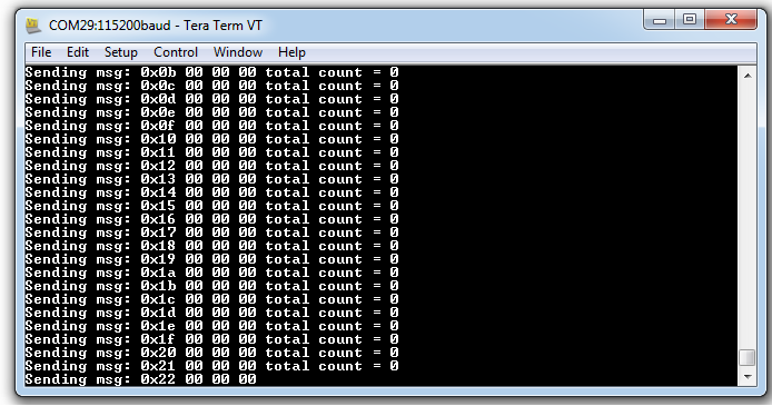
    In the debugger window i am able to see the register IF1DA1 getting incremented every second but the interrupt for ENABLE INTERRUPT ON TRANSMISSION is not getting set.One more check what i did is in the hyper terminal i am receiving the transmitted data but the counter g_ulMsgCount  is not getting incremented.I using LM4F232H5QD evaluation board.

    Thanks,

    Nitin

  • Hello Nitin,

    Careful. Some registers are clear on read. So what happens when debugger and CPU both try to access such register (a matter of time). You can monitor the CANH-CANL lines on a scope. They are differential lines so you would see them moving in the opposite direction. If you have a CAN enabled Logic Analyzer, then it would be more useful to connect it to the CANRX to see what is being received.

    Regards
    Amit
  • Hi Amit,

                  For the above code i am not able to see the g_ulMsgCount counter getting incremented which confirms that no interrupt has occurred for successful transmission.I have attached the screen shot of data received in Hyper terminal.

    As you said i have checked the voltage values across the transceiver which is as follows:

                   1)TX(D): 2.87v(With respect to GND)

                    2)RX(R):3.28v(With respect to GND)

                   3)CANH: 2.27v(With respect to GND)

                   4)CANL: 2.27v(With respect to GND)          

    I have attached the connection details of how the CAN transceiver is connected to LM4F232H5QD.

    Can you pls confirm the connection & let me know why the counter is not getting incremented. Connection Diagram.docx

    Thanks,

    Nitin                                    

  • I am not seeing any code addressing the NMI pin, such as:
    // unlock GPIO PF0, it is the NMI pin and NMI needs to be disabled
    GPIO_PORTF_LOCK_R = GPIO_LOCK_KEY;
    GPIO_PORTF_CR_R = GPIO_PIN_0;

    If you use the F0 pin for anything, you need to do this.

    Once I got beyond this, wiring in a CAN transceiver was easy and CAN was working.
  • Hello Satheesh,

    It seems that there is no receiver and it may not be getting an ACK at all.

    Regards
    Amit
  • Hi John,

                  If we are using PB4 & PB5 for CAN0 whether we need to disable NMI functionality on pin F0. I have pasted my code can you pls tell me wat am i doing wrong as it is not working for me when i am using PB4 & PB5 of CAN0.

    void
    CANIntHandler(void)
    {
    unsigned long ulStatus;
    g_ulMsgCount++;
    //
    // Read the CAN interrupt status to find the cause of the interrupt
    //
    ulStatus = CANIntStatus(CAN0_BASE, CAN_INT_STS_CAUSE);

    //
    // If the cause is a controller status interrupt, then get the status
    //
    if(ulStatus == CAN_INT_INTID_STATUS)
    {
    //
    // Read the controller status. This will return a field of status
    // error bits that can indicate various errors. Error processing
    // is not done in this example for simplicity. Refer to the
    // API documentation for details about the error status bits.
    // The act of reading this status will clear the interrupt. If the
    // CAN peripheral is not connected to a CAN bus with other CAN devices
    // present, then errors will occur and will be indicated in the
    // controller status.
    //
    ulStatus = CANStatusGet(CAN0_BASE, CAN_STS_CONTROL);

    //
    // Set a flag to indicate some errors may have occurred.
    //
    g_bErrFlag = 1;
    }

    //
    // Check if the cause is message object 1, which what we are using for
    // sending messages.
    //
    else if(ulStatus == 1)
    {
    //
    // Getting to this point means that the TX interrupt occurred on
    // message object 1, and the message TX is complete. Clear the
    // message object interrupt.
    //
    CANIntClear(CAN0_BASE, 1);

    //
    // Increment a counter to keep track of how many messages have been
    // sent. In a real application this could be used to set flags to
    // indicate when a message is sent.
    //
    g_ulMsgCount++;

    //
    // Since the message was sent, clear any error flags.
    //
    g_bErrFlag = 0;
    }

    //
    // Otherwise, something unexpected caused the interrupt. This should
    // never happen.
    //
    else
    {
    //
    // Spurious interrupt handling can go here.
    //
    }
    }

    //*****************************************************************************
    //
    // Configure the CAN and enter a loop to transmit periodic CAN messages.
    //
    //*****************************************************************************
    int
    main(void)
    {
    tCANMsgObject sCANMessage;
    unsigned char ucMsgData[4];

    //
    // Set the clocking to run directly from the external crystal/oscillator.
    // TODO: The SYSCTL_XTAL_ value must be changed to match the value of the
    // crystal on your board.
    //
    SysCtlClockSet(SYSCTL_SYSDIV_1 | SYSCTL_USE_OSC | SYSCTL_OSC_MAIN |
    SYSCTL_XTAL_16MHZ);

    //
    // Set up the serial console to use for displaying messages. This is
    // just for this example program and is not needed for CAN operation.
    //
    InitConsole();

    //
    // For this example CAN0 is used with RX and TX pins on port D0 and D1.
    // The actual port and pins used may be different on your part, consult
    // the data sheet for more information.
    // GPIO port D needs to be enabled so these pins can be used.
    // TODO: change this to whichever GPIO port you are using
    //
    SysCtlPeripheralEnable(SYSCTL_PERIPH_GPIOB);

    //
    // Configure the GPIO pin muxing to select CAN0 functions for these pins.
    // This step selects which alternate function is available for these pins.
    // This is necessary if your part supports GPIO pin function muxing.
    // Consult the data sheet to see which functions are allocated per pin.
    // TODO: change this to select the port/pin you are using
    //
    GPIOPinConfigure(GPIO_PB4_CAN0RX);
    GPIOPinConfigure(GPIO_PB5_CAN0TX);

    //
    // Enable the alternate function on the GPIO pins. The above step selects
    // which alternate function is available. This step actually enables the
    // alternate function instead of GPIO for these pins.
    // TODO: change this to match the port/pin you are using
    //
    GPIOPinTypeCAN(GPIO_PORTB_BASE, GPIO_PIN_0 | GPIO_PIN_1);

    //
    // The GPIO port and pins have been set up for CAN. The CAN peripheral
    // must be enabled.
    //
    SysCtlPeripheralEnable(SYSCTL_PERIPH_CAN0);

    //
    // Initialize the CAN controller
    //
    CANInit(CAN0_BASE);

    //
    // Set up the bit rate for the CAN bus. This function sets up the CAN
    // bus timing for a nominal configuration. You can achieve more control
    // over the CAN bus timing by using the function CANBitTimingSet() instead
    // of this one, if needed.
    // In this example, the CAN bus is set to 500 kHz. In the function below,
    // the call to SysCtlClockGet() is used to determine the clock rate that
    // is used for clocking the CAN peripheral. This can be replaced with a
    // fixed value if you know the value of the system clock, saving the extra
    // function call. For some parts, the CAN peripheral is clocked by a fixed
    // 8 MHz regardless of the system clock in which case the call to
    // SysCtlClockGet() should be replaced with 8000000. Consult the data
    // sheet for more information about CAN peripheral clocking.
    //
    CANBitRateSet(CAN0_BASE,SysCtlClockGet(), 500000); //

    //
    // Enable interrupts on the CAN peripheral. This example uses static
    // allocation of interrupt handlers which means the name of the handler
    // is in the vector table of startup code. If you want to use dynamic
    // allocation of the vector table, then you must also call CANIntRegister()
    // here.
    //
    // CANIntRegister(CAN0_BASE, CANIntHandler); // if using dynamic vectors
    //
    CANIntEnable(CAN0_BASE, CAN_INT_MASTER | CAN_INT_ERROR | CAN_INT_STATUS);

    //
    // Enable the CAN interrupt on the processor (NVIC).
    //
    IntEnable(INT_CAN0);

    //
    // Enable processor interrupts.
    //
    IntMasterEnable();

    //
    // Enable the CAN for operation.
    //
    CANEnable(CAN0_BASE);

    //
    // Initialize the message object that will be used for sending CAN
    // messages. The message will be 4 bytes that will contain an incrementing
    // value. Initially it will be set to 0.
    //
    *(unsigned long *)ucMsgData = 0;
    sCANMessage.ulMsgID = 0x500; // CAN message ID - use 1
    sCANMessage.ulMsgIDMask = 0; // no mask needed for TX
    sCANMessage.ulFlags = MSG_OBJ_TX_INT_ENABLE; // enable interrupt on TX
    sCANMessage.ulMsgLen = sizeof(ucMsgData); // size of message is 4
    sCANMessage.pucMsgData = ucMsgData; // ptr to message content

    //
    // Enter loop to send messages. A new message will be sent once per
    // second. The 4 bytes of message content will be treated as an unsigned
    // long and incremented by one each time.
    //
    for(;;)
    {
    //
    // Print a message to the console showing the message count and the
    // contents of the message being sent.
    //
    UARTprintf("Sending msg: 0x%02X %02X %02X %02X",
    ucMsgData[0], ucMsgData[1], ucMsgData[2], ucMsgData[3]);

    //
    // Send the CAN message using object number 1 (not the same thing as
    // CAN ID, which is also 1 in this example). This function will cause
    // the message to be transmitted right away.
    //
    CANMessageSet(CAN0_BASE, 1, &sCANMessage, MSG_OBJ_TYPE_TX);

    //
    // Now wait 1 second before continuing
    //
    SimpleDelay();

    //
    // Check the error flag to see if errors occurred
    //
    if(g_bErrFlag)
    {
    UARTprintf(" error - cable connected?\n");
    SET = 0x01;
    }
    else
    {
    //
    // If no errors then print the count of message sent
    //
    UARTprintf(" total count = %u\n", g_ulMsgCount);
    SET = 0x00;
    }

    //
    // Increment the value in the message data.
    //
    (*(unsigned long *)ucMsgData)++;
    }

    //
    // Return no errors
    //
    return(0);
    }

    Thanks,

    Nitin

  • Hi Sue,
    Can you pls tell how to check whether my PB4 & PB5 pin are configured fine as CAN0 without using the transceiver.As when i send 8 bytes of data(i.e ucMsgData[4]= {0xAA,0x55,0xAA,0x55,0xAA,0x55,0xAA,0x55};) i am not able to see any voltage changes in the CANTX pin.I have tried in both Tiva launchpad & LM4F232 evaluation board.
  • Hello Nitin,

    Should'nt the line

    GPIOPinTypeCAN(GPIO_PORTB_BASE, GPIO_PIN_0 | GPIO_PIN_1);

    be changed to

    GPIOPinTypeCAN(GPIO_PORTB_BASE, GPIO_PIN_4 | GPIO_PIN_5);

    Did you already try this?

    Thanks,

    Sai

  • Hi Sai,

               Thank for your quick response..

               That was one of the reason, now i am able get voltage at CAN0TX(PB5 pin) i.e 1.75v but it stays at that voltage form some time and returns back to 3.3v whether this is due to busoff condition as in my setup i only have single micro & transceiver.

    I am not able to receive any transmit interrupt after the data has been transmitted form TX line wat might be the reason??

    OR  

    whether we need to have two Micro & two transceiver to get the transmit interrupt.  

    Thanks

    Nitin