Part Number: AM263P4
Other Parts Discussed in Thread: SYSCONFIG
Hi,
References: mcu_plus_sdk_am263px_10_02_00_15, AM263P Technical Reference Manual (July 2025)
I have single mode resolver in RDC_SEQUENCER_MODE_0 which is generating 5KHz excitation at excitation frequency amplitude of 140. There are two faults that I am not able to figure out how to clear.
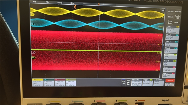
- Excitation Frequency Degradation Diagnostics sin and cos counts are toggling between 218/219 to 469, while expected count is suppose to be between 450 and 550. I see in oscilloscope that zero crossing for sin and cos is occuring at 5KHz but still this fault is not clearing.
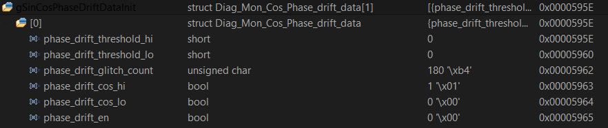
 2. Sine/Cosine Gain Drift and Cosine Phase Drift fault is triggered when going is positive direction but cleared in negative direction of speed.Also, I have observed that gain_drift_threshold_hi, gain_drift_threshold_low, phase_drift_cos_hi and phase_drift_cos_lo are cleared while calling their individual set functions RDC_setDiagnosticsSinCosGainDriftData and RDC_setDiagnosticsCosPhaseDriftData. I am not sure if this is intentional or something that might have been fixed in other versions of SDK.
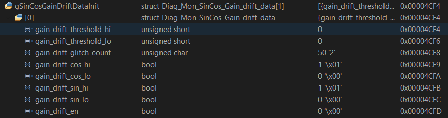
 So, question I have is how can I clear the above-mentioned faults?