Other Parts Discussed in Thread: SYSCONFIG, AM263P4
Hi,
I originally posted this in the incorrect forum (TMDSCNCD263P: FSI Pinmux). Apologies for the duplicate, but figured I would repost here:
I am working on getting FSI working on the AM263 control card. I have a very simple program running, which simply sends a ping frame and receives it:
/* send ping frame*/ status = FSI_setTxFrameType(txBaseAddr, FSI_FRAME_TYPE_PING); status += FSI_setTxFrameTag(txBaseAddr, FSI_FRAME_TAG1); status += FSI_startTxTransmit(txBaseAddr); status += SemaphoreP_pend(&gFsiTxSemObject, ClockP_usecToTicks(FSI_TX_TIMEOUT_US)); if(status != SystemP_SUCCESS) { DebugP_log("failed to send ping frame\r\n"); continue; } DebugP_log("sent ping frame\r\n"); /* receive ping frame*/ status += SemaphoreP_pend(&gFsiRxSemObject, ClockP_usecToTicks(FSI_RX_TIMEOUT_US)); status += FSI_getRxFrameType(rxBaseAddr, &frameType); status += FSI_getRxPingTag(rxBaseAddr, &rxFrameTag); if (status != SystemP_SUCCESS) { DebugP_log("failed to receive ping frame\r\n"); continue; } DebugP_log("received ping frame: frame tag = %u\r\n", rxFrameTag);The program runs flawlessly when running in loopback mode; however, when I short rx to tx with jumper wires, and run in normal mode, the program does not work (no ping frame is received).
My guess is that this is a pinmux issue since loopback mode bypasses the pinmux; however, I can't seem to find anything wrong with my setup. FSI signals are muxed with MCAN signals, but FSI is default because of the pull-up resistor on FSI_MUX_SEL. By the way, this documentation is incorrect (the pull-down resistor is not populated):
The MCAN signals go through a 1:2 signal routing mux. There is a pull-down resistor on the select line of the mux and therefore the MCAN signal routing is the default.
I am also fairly certain that my AM263 Pinmux is setup correctly. From the PROC1592E2 schematic:
| FSIRX2_CLK | J2 |
| FSIRX2_DATA0 | G4 |
| FSIRX2_DATA1 | J3 |
| FSITX2_CLK | G3 |
| FSITX2_DATA0 | H2 |
| FSITX2_DATA1 | G1 |
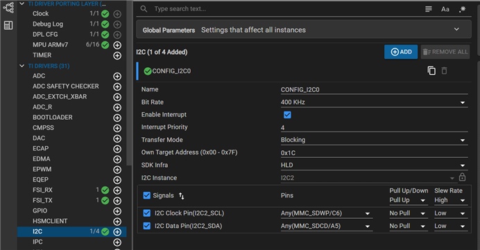
Sysconfig setup:


I also don't think there is anything wrong with my interrupt setup because I don't believe the loopback program would work if there was something misconfigured here.
Am I missing something? Any recommendations on where to look next?
Thanks,
Thanks,
-Jared