This thread has been locked.

If you have a related question, please click the "Ask a related question" button in the top right corner. The newly created question will be automatically linked to this question.

AM2431: AM2431 – RESETSTATz remains LOW, no clock observed on MCU_OSC pins

Part Number: AM2431
Other Parts Discussed in Thread: UNIFLASH, AM2432

Hello TI Team,

I am currently working on AM2431 custom board bring-up and would like guidance regarding a reset and clock-related issue I am observing.


Problem Description

  • The device is not responding over JTAG during programming/debug attempts.
  • All required power rails are present and within nominal voltage levels.
  • During reset signal checks, RESETSTATz remains LOW.

Reset / Status Measurements

Measured after power-up:

Signal Measured Voltage
MCU_PORz ~1.8 V (HIGH)
PORz_OUT ~3.3 V (HIGH)
MCU_RESETz ~3.3 V (HIGH)
RESET_REQz ~3.3 V (HIGH)
RESETSTATz LOW
 

No clock activity or pulses are observed on either node MCU_OSCO_XI, MCU_OSCO_XO when measured with an oscilloscope.


Power Consumption

  • Input supply: 5 V
  • Total current draw: approximately 66 mA

Request for Guidance

I would appreciate clarification on:

  • Expected behavior of RESETSTATz during initial power-up
  • Relationship between clock generation and internal reset release
  • Conditions required for JTAG availability during early bring-up
  • Whether absence of clock activity can result in RESETSTATz remaining LOW

Any insights into RESETSTATz behavior, clock dependency, or bring-up expectations for AM2431 would be very helpful.
If need any further details required, please let me know. 

Thank you for your time and support.

Best regards,
Manikandan V

  • Hello Manikandan V,

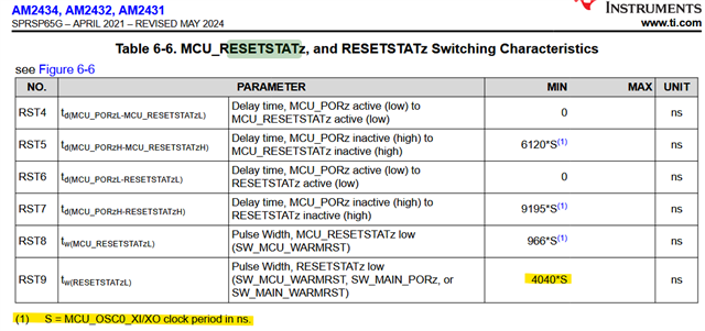
    Yes, RESETSTATz de-assertion has dependency on system clock to complete the internal reset sequence. Please see a snapshot from datasheet:

    Regards,

    Stan

  • Hello Manikandan V,

    Regarding the impact of different reset inputs on the AM243x RESETSTATz output signal behavior you may want to check the following E2E FAQ:

    Custom board HW design: processor reset inputs reset status outputs and connection recommendations 

    The following FAQ excerpt contains some important details regarding RESETSTATz output behavior for the AM64x and AM243x SoC:

    Thanks

    Kind Regards,

    Anastas Yordanov

  • Hello Manikandan

    Checking if you are able to share the schematics to do a quick check and provide possible suggestion.

    Is the power architecture PMIC based or discrete?

    Is the clock source crystal or oscillator.

    Regards,

    Sreenivasa

  • Hello Manikandan

    Additionally, can you please verify the slew of MCU_PORz.

    Slow slew can glitch the internal reset.

    Faster the better.

    Can you please capture the waveform.

    Regards,

    Sreenivasa


  • Hi Sreenivasa,

    Please find the attached schematic PDF for reference.
    Kindly ignore the index pages, block diagrams, and GPIO mapping tables, as those sections have not yet been updated to reflect the current design.

    This design uses a discrete power architecture (non-PMIC based).
    For the clock source, a 25 MHz crystal is used:

    • Part number: ABM10W-25.0000MHz-8-K1Z-T3

    • Crystal specification: 25.0000 MHz, 8 pF, SMD


    Bring-up Observations

    During initial bring-up, I observed that MCU_PORz was being released earlier than expected, before all required power rails became valid.

    Upon further investigation, I found that the core voltage monitor IC was not behaving as intended. Specifically, the monitor was not holding the reset pin low until the sense voltage became valid. Instead, the reset signal was going HIGH as soon as the pull-up supply became available. As a result, the reset timing and power-up sequencing were not as expected.

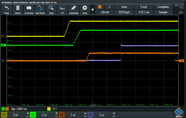
    Please refer to the attached waveform image showing the initial faulty behavior, where MCU_PORz is asserted early:

    • yellow : VCC3V3_PREREG

    • green: VCC_3V3_SYS

    • Blue: PORz

    • Orange: VDD_CORE


    Temporary Modification for Reset Validation

    To obtain a valid reset signal, I isolated the faulty voltage monitor circuit.
    For testing purposes, I sourced the reset signal from a working EVM board and connected it to the PORz net of the custom board (R171 was removed and the EVM reset signal was injected into the PORz net).

    With this modification:

    • MCU_PORz now goes HIGH after the VDD_CORE rail becomes valid

    • Reset is released approximately 10 ms after the core supply reaches its nominal level

    Please see the attached waveform image showing the corrected behavior.

    • yellow : VCC3V3_PREREG

    • green: VCC_3V3_SYS

    • Blue: PORz

    • Orange: VDD_CORE


    Additional Notes

    1. VDD_CORE voltage is currently measured at 0.83 V, not 0.85 V.
      The VDD_CORE regulator feedback resistor R118 was intentionally designed for 0.83 V. This was due to a resistor procurement issue; the current schematic version shows an incorrect feedback configuration (0.75 V), which will be corrected in the next revision.

    2. The reset signal sourced from the EVM is only used for validation.
      The 5 V main input for the custom board is also being supplied from the same EVM board during this testing.


    Even after implementing the above modifications, there is no change observed in the RESETSTATz and MCU_RESETSTATz signals. Both signals continue to remain in the LOW state.

    Please let me know if you require the complete power-up sequence waveforms for all rails or any additional measurements.

    Thanks and regards,
    Manikandan V

    PROC_REVB_02-02-2026.pdf

  • Hello Manikandan

    Thank you.

    Can you probe the VDD_CORE, clock and MCU+PORz

    The MCU_PORz should be delayed by 9.5ms min after VDD_CORE ramps and released only after the clock is stable.

    Regards,

    Sreenivasa

  • Hi sreenivasa, 

    Thanks for the response, 

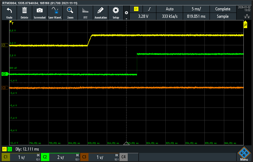
    Please find the below waveform VDD CORE - Ch1 , MCU_Porz - ch2 , CLOCK - Ch3


    VDD core --> MCU_PORz ---> 12.11ms delay 

    There no Clock activity --> Probed in R138 resistor 

    Note: Please review the reset signal section on the schematic and i removed few of the power supply sections which we dont want in our application (Eg: Ethernet and Test header supply's)  FYI. 

    Thanks, 

    Manikandan V 

  • Hello Manikandan 

    R140 0R seems populated.

    This is required only when oscillator is used.

    Can you please DNI and check.

    Please probe with a high Z scope probe.

    Regards,

    Sreenivasa

  • Hi Sreenivasa,

    Thank you for your support.

    After removing R140, the clock is now generated correctly. I am able to observe both RESETSTATz and MCU_RESETSTATz transitioning to the HIGH state. I also performed a JTAG connection test, and it is working without any issues.

    Thank you to you and others in this thread for the guidance and assistance.

    Please find the attached waveform/image for your reference.

    Additionally, could you please review my DDR, eMMC, OSPI, and USB interface circuits, along with their associated reset circuits. This would be helpful for the next stages of bring-up.

    Thanks and regards,
    Manikandan V

  • Hello Manikandan

    Thank you for updating the progress and happy to see the issue resolved.

    could you please review my DDR, eMMC, OSPI, and USB interface circuits, along with their associated reset circuits. This would be helpful for the next stages of bring-up.

    Can you please update if you are working with any of the TI sales or TI support members.

    Regards,

    Sreenivasa

  • Hello Manikandan

    In case you are not working with any of the TI field team, please submit a separate E2E for each of the peripheral lining this E2E and add any concerns or focus review points for the experts to support.

    Once you add the threads, please add the link to this thread.

    Regards,

    Sreenivasa

  • Hello Sreenivasa,

    Understood. I will create separate E2E threads for each peripheral and include specific concerns or focus areas for review. Once the threads are created, I will add the corresponding links to this thread.

    Regards,
    Manikandan V

  • Hello Manikandan

    Thank you and noted.

    In case you are currently not working with any TI sales or support, i would recommend that you reach out to them.

    If you are able to confirm you are not working with ant TI field, i can check with the TI filed team on the process.

    Regards,

    Sreenivasa

  • Hello Sreenivasa,

    Thank you for the message.

    Currently, I am not working with any TI sales or support field team. Could you please check with the TI field team regarding the process and advise on the next steps?

    Regards,
    Manikandan V

  • Hello Manikandan

    Thank you, i will check with the sales team and update you.

    Regards,

    Sreenivasa

  • Hi Sreenivasa,

    Regarding the reset signal currently being sourced from the EVM board, we are presently dependent on the EVM for the VDD_CORE sense–based reset signal used for MCU_PORz. Our goal is to remove this dependency on the EVM board.

    Could you please let us know if there are any alternate pins, status signals, or recommended methods that can be used to generate or qualify the MCU_PORz signal with the required timing? If there is any internal status or external signal that can be utilized to meet the reset delay requirement, guidance on the same would be helpful.

    Please advise on a suitable approach to resolve this.

    Regards,
    Manikandan V

  • Hello Manikandan

    Thank you.

    I split theMCU_PORz into a separate thread for follow-up

    (9) RE: AM2431: AM2431 – MCU_PORz generation - Processors forum - Processors - TI E2E support forums

    I will add my comments to the other thread

    Regards,

    Sreenivasa

  • Hello Manikandan

    Please refer below for reaching out to TI sales.

    please ask them to send an email to reach2ti_india@list.ti.com. Our India MM team is on the mailing list and can assist if possible. 

    Regards,

    Sreenivasa

  • Hi Sreenivasa,

    Thank you for the information. I will coordinate with the relevant team to reach out as suggested.

    Thanks and regards,
    Manikandan V

  • Hello Manikandan

    Thank you for the note.

    Regards,

    Sreenivasa

  • Hi Sreenivasa,

    I have sent an email to the mail ID you shared. However, we have not received any response yet. Could you please let us know if anything is missing from our side, or if there are any limitations or conditions for getting field support?

    Thanks,
    Manikandan V


  • Hello Manikandan

    Thank you for the note.

    I assume you have include the application and other information for the sales team.

    Please give a few days for them to respond.

    Regards,

    Sreenivasa

  • Hi Sreenivasa,

    Thanks for the update. I believe we have shared the necessary information with the sales team; let’s wait for a few more days for their response.

    In parallel, we are facing another issue related to OSPI booting on our AM2431 custom board. Specifically, the OSPI flash erase operation succeeds, but flashing the image fails, and we consistently encounter a flash error during OSPI boot.

    Summary of the issue:

    • SBL NULL (HS-FS) boots successfully via UART and SYSFW/core initialization completes.

    • OSPI flash is detected correctly (JEDEC ID and SFDP read OK).

    • OSPI Flash IO and write–read tests pass.

    • Block erase operation fails, as reported by OSPI Flash Diagnostics.

    • During UART Uniflash, flash erase may start but flashing the SBL image fails.

    • When switching to OSPI boot, no UART logs are observed.

    • OSPI waveforms show CLK/CS/DQ activity during the erase command, but no further bus activity after erase.

    Overall, OSPI read/write access works, but erase/flash operations do not complete successfully, which is blocking OSPI boot.

    Also, we have an active TI E2E forum thread for this issue. I am sharing the forum link for your reference. If you notice anything similar from your experience or have faced a related issue earlier, your inputs would be very helpful for us.

     RE: AM2431: AM2431 – UART Uniflash to OSPI Flashing Failure with HS-FS SBL on Custom Board 

    Please let us know if you have seen a similar issue or have any guidance on how to proceed.

    Thanks and regards,
    Manikandan V

  • Hello Manikandan, 

    Thank you.

    In case you are not working with any of the TI field team, please submit a separate E2E for each of the peripheral lining this E2E and add any concerns or focus review points for the experts to support.

    Once you add the threads, please add the link to this thread.

    Not sure if you had a chance to start separate thread.

    In case you can add a E2E request for OSPI section review, i have a few finding that i can add that will require changes to the pulldown value and populating the pullups.

    Regards,

    Sreenivasa

  • Hello Manikandan,

    Thank you.

    I see Vaibhav supporting the thread and should be fine.

    Also, we have an active TI E2E forum thread for this issue. I am sharing the forum link for your reference. If you notice anything similar from your experience or have faced a related issue earlier, your inputs would be very helpful for us.

     RE: AM2431: AM2431 – UART Uniflash to OSPI Flashing Failure with HS-FS SBL on Custom Board 

    Please let us know if you have seen a similar issue or have any guidance on how to proceed.

    Regards,

    Sreenivasa

  • In case you can add a E2E request for OSPI section review, i have a few finding that i can add that will require changes to the pulldown value and populating the pullups.

    Hi Sreenivasa,

    Thank you for the clarification and guidance.

    Understood. Since Vaibhav is already supporting the current E2E thread, we will continue to work with him on this issue. As suggested, we will also consider raising a separate E2E request for an OSPI section review and will share the link in the existing thread once it is created.

    In the meantime, please let us know if there are any concerns related to populating or depopulating components in the OSPI section. You had mentioned earlier that there may be a few findings related to pull-down values and required pull-ups in the OSPI interface. If you could share those observations or recommendations, it would be very helpful for us to address them quickly and move toward resolving the issue.

    Vaibhav is currently supporting us on the forum, and if possible, your additional inputs or thoughts would greatly help us expedite the closure of this issue.

    Thanks again for your support.

    Regards,
    Manikandan V

  • Hello Manikandan,

    Please make the below changes and do a quick check.

    Please populate D0//D7 pullup

    Reduce the OSPI_CLK pulldown to 10K

    Regards,

    Sreenivasa

  • Hi Sreenivasa,

    As per your guidance, we have made the following hardware changes and performed a quick verification:

    • OSPI CLK pulldown resistor changed to 10 kΩ

    • OSPI data lines DQ0 to DQ7 pull-up resistors (10 kΩ) populated

    However, even after these changes, the same flashing issue is still observed.

    For your reference, please find the UART Uniflash debug log captured after the above modifications:

    ~/ti/mcu_plus_sdk_am243x_11_01_00_17/tools/boot $ python3 uart_uniflash.py -p /dev/ttyUSB0 --cfg=sbl_userbuilt/userbuilt_sbl_null.cfg
    
    Parsing config file ...
    Parsing config file ... SUCCESS. Found 3 command(s) !!!
    
    Executing command 1 of 3 ...
    Found flash writer ... sending sbl_userbuilt/sbl_uart_uniflash.Release.hs_fs.tiimage
    
    Sent flashwriter sbl_userbuilt/sbl_uart_uniflash.Release.hs_fs.tiimage of size 322941 bytes in 29.17s.
    
    Executing command 2 of 3 ...
    Command arguments : --operation=erase --flash-offset=0x0 --erase-size=0x100000
    Sent flash erase command.
    [STATUS] SUCCESS !!!
    
    Executing command 3 of 3 ...
    Command arguments : --file=sbl_userbuilt/sbl_null.Release.hs_fs.tiimage --operation=flash --flash-offset=0x0
    Sent sbl_userbuilt/sbl_null.Release.hs_fs.tiimage of size 282997 bytes in 28.06s.
    [STATUS] ERROR: Flashing failed !!!
    
    All commands from config file are executed !!!

    Kindly review the above and let us know if there are any additional hardware checks or OSPI configuration updates recommended from your side.

    If you have any known working OSPI booting binaries or reference files for the AM2431, could you please share them with us?
    We would like to test the same from our end to rule out any configuration-related issues.

    We currently have a doubt whether some configuration changes during the AM2432 to AM2431 conversion, or any security-related options, might be contributing to this behavior.


    Thanks & Regards,
    Manikandan V

  • Hello Manikandan 

    Thank you.

    Please retain the hardware changes - these are recommended.

    Please work with Vaibhav to further debug the issue you are facing.

    Regards,

    Sreenivasa