This thread has been locked.

If you have a related question, please click the "Ask a related question" button in the top right corner. The newly created question will be automatically linked to this question.

AM2431: Capacitor connected to the pin of the CAP_*

Part Number: AM2431

Hi,

The datasheet has been revised from REV G to REV H.
Regarding the section:
(Signal Descriptions - Power Supply): Updated the table notes associated with the CAP_VDDSx pins to clarify the need for capacitance derating and describe additional connectivity options .................................. 89
It states:

This pin must always be connected via a 6.3V or greater, 0.8uF to 1.5uF capacitor to VSS if the respectiVe VDDSHVx pin is eVer operated at 3.3V. The capacitor selected must proVide a capacitance within the defined range after it has been derated for DC bias.

My question is:
What happens if the capacitance is smaller than 0.8uF or larger than 1.5uF?


EVen when using capacitors with tolerance +-10% and temperature characteristic X7R (+-15%), the requirement cannot be satisfied without considering DC bias.
Example calculations:

1.0uF X7R, tolerance +-10% , temperature Variation +-15%
Max: 1.0 × (1.10 × 1.15) = 1.265uF
Min: 1.0 × (0.90 × 0.85) = 0.765uF

1.5uF X7R, tolerance +-10% , temperature Variation +-15%
Max: 1.5 × (1.10 × 1.15) = 1.897uF
Min: 1.5 × (0.90 × 0.85) = 1.147uF

Regards,

Futoshi

  • Hi,

    I found a related Q&A.

    [FAQ] AM625 / AM623 / AM620-Q1 / AM62L / AM62Ax / AM62D-Q1 / AM62Px / AM64x / AM243x Design Recommendations / Custom board hardware design – Queries related to CAP_VDDSx CAP_VDDS - Processors forum - Processors - TI E2E support forums

    According to it, when using 3.3 V, the CAP_VDDSx voltage follows half of CAP_VDDSx, i.e., 1.65 V. The following capacitors are given as examples:

    • CL03A105KP3NSNC
      1 µF ±10% 10 V Ceramic Capacitor, X5R, 0201 (0603 Metric)

    • GRM155R61A105KE15D
      SMD Multilayer Ceramic Capacitor, 1 µF, 10 V, 0402 [1005 Metric], ±10%, X5R

    For CL03A105KP3NSNC, the DC-bias at 1.65 V (which is half of 3.3 V) is −35%.
    The minimum capacitance is:
    1 µF × 0.90 × 0.85 × 0.65 = 0.4975 µF.

    For GRM155R61A105KE15D, the DC-bias at 1.65 V is −6%.
    The minimum capacitance is:
    1 µF × 0.90 × 0.85 × 0.94 = 0.7191 µF.

    Both are below 0.8 µF. How should we handle this?

    Regards,

    Futoshi

  • Hello Futoshi

    Thank you for the query.

    The capacitor part numbers are added as example guidelines for customer to looks for similar components.

    The LDO output capacitor range has been recommended for the internal LDO stability. 

    It is highly unlikely that the caps will see all the parameters to be on the worst case and also the End equipment operating at the worst temperature continuously.

    Regards,

    Sreenivasa

  • Hello Futoshi

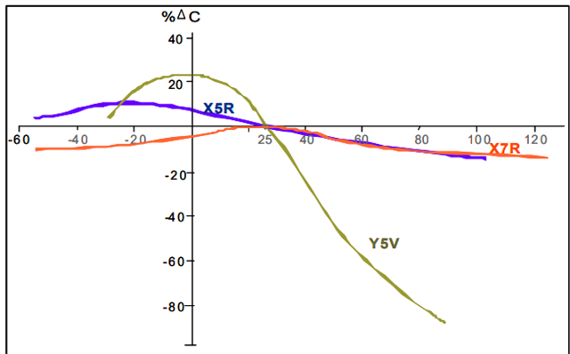
    The temp characteristic for the below capacitors seems similar to the other.

    CL03A105KP3NSNC,

    The graph show the temp characteristics to be better than the above spec

    Regards,

    Sreenivasa

  • Hello Futoshi

    If there is an use case where the ambient temperature of the End Equipment is expected to be at the corners of the specified operating temperature, a better performance capacitor may need to be selected which is likely not a requirement.

    Regards,

    Sreenivasa

  • Hello Futoshi

    Checking if you have the initial capacitance distribution graph for the 10% capacitors that you may have received from any of the suppliers you may have been working with.

    Regards,

    Sreenivasa

  • Hi, Sreenivasa

    Thank you for your response.

    The capacitor you listed does not meet the requirement.

    In particular, CL03A105KP3NSNC has a DC‑bias characteristic of −35%, which already makes it impossible to maintain 0.8 µF or more.

    Even if an initial capacitance distribution graph exists, we must assume ±10% variation because the capacitor manufacturer specifies ±10%.

    I believe there are no capacitors on the market that satisfy these conditions.

    What will happen if the capacitance becomes smaller than required?

    For example, will the LDO output oscillate, or will the system become more susceptible to noise?

    Please explain the possible issues.

    Regards,

    Futoshi

  • Hello Futoshi

    In particular, CL03A105KP3NSNC has a DC‑bias characteristic of −35%, which already makes it impossible to maintain 0.8 µF or more.

    You need to consider DC bias for 1.65V on a rated capacitor voltage of 10V.

    I would expect the variation to be few % based on the ration of rated vs applied.

    • GRM155R61A105KE15D
      SMD Multilayer Ceramic Capacitor, 1 µF, 10 V, 0402 [1005 Metric], ±10%, X5R

    You could consider the above.

    The capacitor you listed does not meet the requirement

    I have listed some of the capacitor part numbers as a starting point for customers to select. These are not the recommended part numbers.

    Even if an initial capacitance distribution graph exists, we must assume ±10% variation because the capacitor manufacturer specifies ±10%.

    The recommendation is to work with the capacitor supplier for calculating the variation as well as the drift.

    Regards,

    Sreenivasa

  • Hi, Sreenivasa

    Even after coordinating with multiple capacitor suppliers, we have confirmed that no single capacitor can meet the required specification.

    To satisfy the requirement, multiple capacitors in parallel would be necessary, but we unfortunately do not have enough PCB space to place more than one capacitor for each CAP_VDDSx pin.

    Given these constraints, we would like to proceed by accepting that we cannot meet the requirement.

    Could you please explain what issues or risks may occur if the capacitance requirement is not satisfied?

    Thank you for your support.

    Best regards,

    Futoshi

  • Hello Futoshi

    Given these constraints, we would like to proceed by accepting that we cannot meet the requirement.

    Understand, the recommendation is to choose the cap that is as close to the allowed cap range. Using 10% tolerance, 10V or 16V cap is recommended.

    Could you please explain what issues or risks may occur if the capacitance requirement is not satisfied?

    I suspect the concern is related to load transients.

    I am checking internally and will update in case i hear from the expert.

    FYI, we do not have customers reporting issues related to cap_vddsx affecting the processor performance on the Am64x or the AM72x processor families.

    Regards,

    Sreenivasa 

  • Hi,Sreenivasa

    Thank you for your support.

    I will wait for the response from the expert.

    Thank you in advance for your continued assistance.

    Best regards,

    Futoshi

  • Hello Futoshi

    Will do.

    Regards,

    Sreenivasa