This thread has been locked.

If you have a related question, please click the "Ask a related question" button in the top right corner. The newly created question will be automatically linked to this question.

TMS570LS1227: Maximum EMIF Clock Frequency

Part Number: TMS570LS1227

Hello,

Looking at the datasheet for our device, table 6-28 states that the minimum EMIF clock period is 11 nanoseconds which equates to 90 MHz. 

Before I saw this in the datasheet, I configured the EMIF to run at 180 MHz and it seems to result in correct timing still.  My configuration:


Asynchronous Mode
Strobe Mode: enabled
Setup Wait States: 0
Strobe Wait States: 31
Hold Wait States: 7
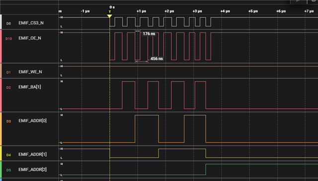
Expected Strobe Timing: (31 + 1) * (1/180000000) = 177.7ns
Measured Strobe Timing: 176ns

I want to confirm that 90 MHz is indeed the maximum EMIF clock frequency since the timings seem to still be accurate at 180 MHz.

PS I'm trying to add images but the uploads keep failing.  I will try to add images later.

Thanks,

Will

  • Hi WIll,

    The VCLK3 is the clock source for EMIF module. The VCLK3 frequency is divided down from the HCLK domain frequency by a programmable divider (/1 to /16).

    To interface a asynchronous memory, the EMIF can use up to 90MHz EMIF clock (min clock cycle is 11ns). For using a synchronous memory, the clock should be 45MHz (min cycle time is 22ns)

    What is strobe wait states? How do you measure this? 

    For EMIF timing, we have read strobe time (nOE is LOW) and write strobe time (nWE is LOW).

  • I want to confirm that 90 MHz is indeed the maximum EMIF clock frequency since the timings seem to still be accurate at 180 MHz.

    At 180MHz EMIF clock, the EMIF will not read/write the EMIF memory properly. It violates the spec defined in the device datasheet.

  • Hi QJ,

    Thanks for the response.  Yes, the HCLK is running at 180MHz and I have the divider set to /1.  

    >>>What is strobe wait states? How do you measure this?

    Maybe I was not using the terminology used by the Technical Reference Manual.  The strobe wait states is the R_STROBE and W_STROBE register settings for strobe width in EMIF clock cycles.

    I measured my strobe timing by measuring how long nOE and nWE are low for.  Below, see a screenshot of my capture that shows the nOE low time at 176ns, aligning with my math in the original post.

    You say at 180MHz clock it violates spec, but what breaks if we use 180MHz?  It seems to work as expected.  Overall, I think we can achieve similar timing at 90MHz by dividing our wait state settings by 2 so perhaps it's not a huge deal to drop to 90MHz.  We mainly wanted to confirm the 90MHz maximum because everything seems to work at 180MHz.  


    Thanks,

    Will

  • Hi Will,

    Configuring the EMIF clock to 180 MHz when the datasheet specifies a maximum of 90 MHz is a 2x "overclock." While your current write strobe timings might appear functional, this practice violates the design parameters of the silicon and carries significant risks regarding system stability, data integrity, and component longevity. 

    Increasing the frequency drastically reduces the time available for data setup and data hold. The data must remain valid for a certain time before and after the clock edge, which is often violated (setup or hold) when overclocking.

    The data signals or address signals might not be stable at the receiving memory device within the drastically reduced clock window (5.55ns at 180MHz vs. 11.1ns at 90MHz). You may experience random, silent data corruption, where the memory writes incorrectly, but the EMIF peripheral does not report an error.

    It is highly recommended to stick within the 90MHz specification.