This thread has been locked.

If you have a related question, please click the "Ask a related question" button in the top right corner. The newly created question will be automatically linked to this question.

MSPM0G1507: When communicating in Fast-mode (400kHz), the controller side shifts the data by 1 byte.

Part Number: MSPM0G1507
Other Parts Discussed in Thread: SYSCONFIG, , MSPM0G3507

Hi experts,

When communicating in Fast-mode (400kHz), the controller side shifts the data by 1 byte. Clock Stretch is enabled on both the controller and the target, but the issue still occurs.

I am using the following software(mspm0_sdk_2_10_00_04).
  • i2c_controller_rw_multibyte_fifo_interrupts
  • i2c_target_rw_multibyte_fifo_interrupts
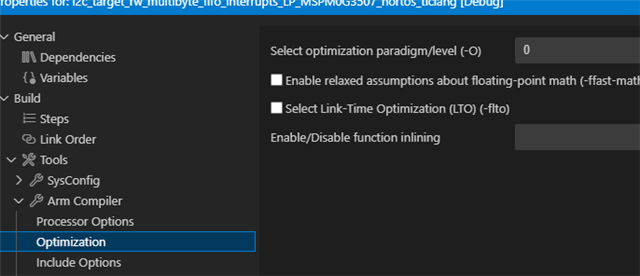
  • I only set the controller side to 400kHz from Sysconfig and switched the clock stretching function ON/OFF for both sides, and Ichanged the compiler optimization level to 0. I have not modified the .c file. 

Q1: Is there any setting I might have overlooked?
Q2: Also, besides using DMA, are there any effective countermeasures for this kind of situation?

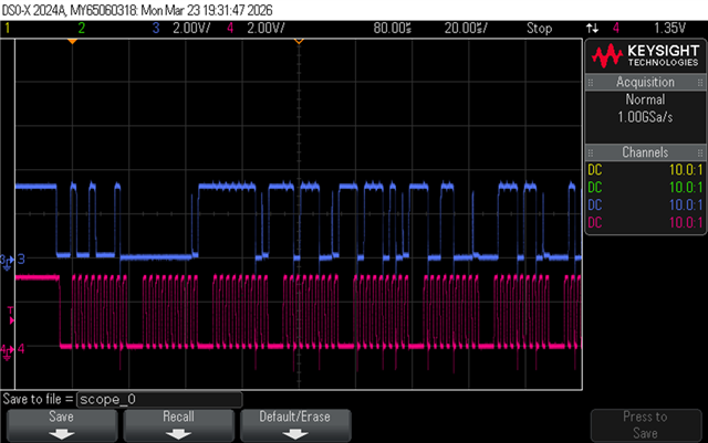
In conclusion, it seems that the target side transmission is not keeping up. When I look at the waveform, the target side sends dummy data for the first byte. If Clock Stretch is enabled on the target side, 0x08 is sent as dummy data; if disabled, 0x00 is sent. From the second byte onward, data is sent in order as 0x00, 0x01, etc. The receive buffer (gRxPacket) on the target side is receiving correctly, and the transmit buffer (gTxPacket) is also copying data correctly. Since I cannot directly check TXFIFO, I looked at STXDATA, and 0x0F is stored.

Best regards,
O,H

  • It seems to occur when the clock stretch of the target is disabled

    Are you sure? A mentioned below

    f Clock Stretch is enabled on the target side, 0x08 is sent as dummy data;

    Dose the 0x08 is correct data that expected?

    One more question is if change the frequency to 100k, dose the issue happen or not?

  • Hi Gary,

    Dose the 0x08 is correct data that expected?

    No. 

    One more question is if change the frequency to 100k, dose the issue happen or not?

    It occurs when the frequency exceeds 250kHz.

    Best regards,
    O.H

  • Hi Gary,

    Sorry. I will rewrite the description including the results of the re-examination due to insufficient explanation.

    The verification results in my EVM environment are making things complicated, but I will reiterate our purpose. Our purpose is to communicate at 400kHz with the target's clock stretching OFF.
    My customer is communicating at 400kHz with G1507 as the target and clock stretching OFF. The controller performs Write→Read. G1507 is written once by the controller, and then returns the written data as is in response to the controller's Read request. (This is exactly the operation of "i2c_target_rw_multibyte_fifo_interrupts_LP_MSPM0G3507_nortos_ticlang".) The problem is that the data returned to the controller is shifted by 1 byte. The same result can be seen with EVM.
    Our question: Please tell us how to deal with this phenomenon where the data is shifted by 1 byte?

    In the customer's environment, G1507 is the target and another CPU is the controller.
    In my environment, one G3507EVM is the target and another G3507EVM is the controller.
    When the target's clock stretching is OFF and communication is at 400kHz:
    The expected value in the customer's environment is 0xFE->0xDC, but when the controller reads it, it becomes 0x00->0xFE.
    In my environment, the expected value is 0x00->0x01, but when the controller reads it, it becomes 0x00->0x00.

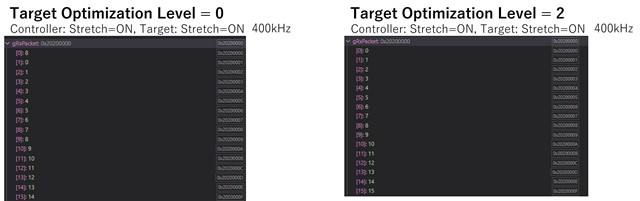
    As a result of re-experimenting in my EVM environment, I found that there is a difference depending on the Optimization Level of the target.
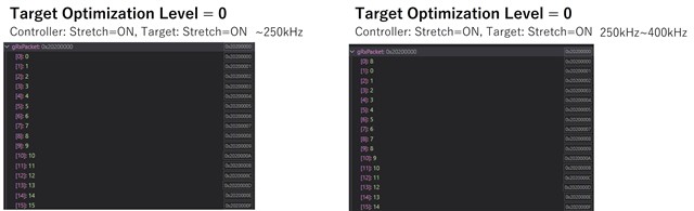
    When the target's clock stretching is ON and communication is at 250kHz or higher:
    If the target's Optimization Level is 0, a problem occurs. If the target's Optimization Level is 2, no problem occurs. 
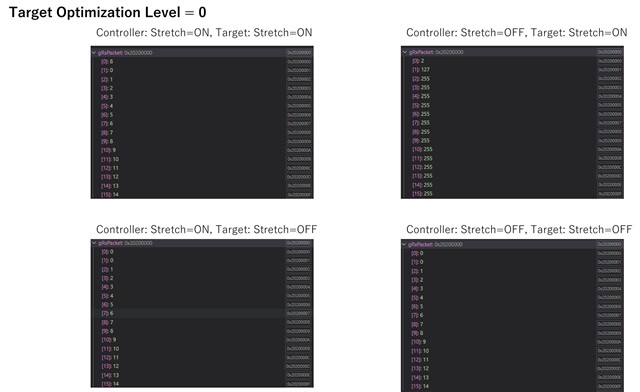
    The figure below shows the result of monitoring gRx/TxPacket on the controller side.
    The figure below shows the result of monitoring gRx/TxPacket on the target side, which is always the same.
    Other patterns are attached for reference.
    Best regards,
    O.H

  • Hi O.H

    For this issue is happen due to the I2C clock speed too fast that not reserve enough time for I2C slave to move the data from TX buffer to the TX FIFO.

    After that test it need about 8us to move the data from TX buffer to TX FIFO, but the 400k clock one cycle just 2.5us that is not enough for the data transfer, so the first byte will always 0x00 that used for data move. To solve the issue, I help to modify the code that make the data move after the data received finished of the stop interrupt and skip the TX FIFO flush in the start interrupt. The code you can refer to 

    4442.i2c_target_rw_multibyte_fifo_interrupts_LP_MSPM0G3507_nortos_ticlang.zip

  • Hi Gary,

    Thank you for your support.

    To solve the issue, I help to modify the code that make the data move after the data received finished of the stop interrupt and skip the TX FIFO flush in the start interrupt. The code you can refer to 

    4442.i2c_target_rw_multibyte_fifo_interrupts_LP_MSPM0G3507_nortos_ticlang.zip

    I have checked the operation of the project you provided. I confirmed that clock stretching on the target side is OFF and used it without making any changes.

    As a result, there were no issues at 400kHz when Optimization Level=2(or 1) was set. However, when Optimization Level=0 is set, problems occur if the frequency exceeds 355.5kHz. (No issues up to 320kHz)

    Q: Is there a way to communicate at 400kHz with clock stretching OFF on the target side and Optimization Level=0? Do I have to set Optimization Level=2 (or 1)?

    Best regards,
    O.H

  • I confirmed that clock stretching on the target side is OFF and used it without making any changes.

    What do you mean of make any changes? 

    The demo is work well to communicate at 400kHz with the target's clock stretching OFF. You can see the wave form capture by Saleae.

    https://e2e.ti.com/cfs-file/__key/communityserver-discussions-components-files/908/7120.Session-0.sal

    The data have any shift at 400khz.

    I also try to build the project with optimization to 0 and it work with no issue.

    Did you try the code I shared to you?

  • Hi Gary,

    Thank you for youreply.

    What do you mean of make any changes? 

    I only changed the optimization level. I tested levels 0, 1, and 2. In my environment, the 1-byte offset occurs only at level 0. I confirmed this from both the waveform and the variables in CCS.

    Her is my customer feedback.

    For this issue is happen due to the I2C clock speed too fast that not reserve enough time for I2C slave to move the data from TX buffer to the TX FIFO.

    After that test it need about 8us to move the data from TX buffer to TX FIFO, but the 400k clock one cycle just 2.5us that is not enough for the data transfer, so the first byte will always 0x00 that used for data move.

    Q3: Could you please explain this using something like a timing chart?
    I believe there is still some margin of about 20 µs because there are 9 clock cycles from START to the slave address phase.

    To solve the issue, I help to modify the code that make the data move after the data received finished of the stop interrupt and skip the TX FIFO flush in the start interrupt.

    I also considered the end of STOP, but since it does not work in the restart pattern (repeated START without STOP). So I am thinking of a method where the TXFIFO is filled in advance at the timing of the previous receive RxFIFO trigger (threshold = 1).
    Q4: Could you please let me know if there are any concerns with this method, or if there is a recommended approach?

    Best regards,
    O.H

  • I only changed the optimization level. I tested levels 0, 1, and 2. In my environment, the 1-byte offset occurs only at level 0. I confirmed this from both the waveform and the variables in CCS.

    Dose customer use code I shared before?

    I believe there is still some margin of about 20 µs because there are 9 clock cycles from START to the slave address phase

    No, the start interrupts if filed after the address bit fully received that mean just two clocks(about 5us) remains for the data move.

    Q4: Could you please let me know if there are any concerns with this method, or if there is a recommended approach?

    If in repeat start condition you can can move the data before trigger repeat start. 

  • Hi Gary,

    Sorry for late reply.

    Since this thread is not functioning properly on my side, I would like to continue the discussion in the thread below.
    (+) MSPM0G1507: When communicating in Fast-mode (400kHz), the controller side shifts the data by 1 byte in repeated start operation - Arm-based microcontrollers forum - Arm-based microcontrollers - TI E2E support forums

    My customer have confirmed that the code you suggested, in which the data is updated in the STOP interrupt, works correctly and does not cause any issues. The next question is about operation with repeated START, where no STOP occurs.

    Best regards,
    O.H

  • Ok, will close this thread first