Part Number: LP-XDS110
Other Parts Discussed in Thread: AM3358, TMDSEMU110-U
Hello, we are attempting to establish a JTAG connection from the LP-XDS110 to BeagleBone Black, which runs the AM3358. Based on TI resources there is (apparently) no cable that can go from the LP (10 pin) to the Beagle (CTI-20 connector soldered on). So we are wiring it directly.
To start we are tapping the larger 20-pin connector on the back of the LP as it also appears to have the standard JTAG signals. See image below -- showing the LP's 20-pinout and the Beagle schema of the CTI20. From the LP we are utilizing TMS (white wire), TDI, TDO, 3V3, TCK, nRST and GND (grey). The color coding indicates the wiring.

Then when we try to connect to the Beagle, CCS says: “The value is ‘-233’ (0xffffff17). The title is ‘SC_ERR_PATH_BROKEN’ …. The JTAG IR and DR scan-paths cannot circulate bits, they may be broken.“ Entire error log below.
We hooked up the scope to TDI, TDO and TCK. During a connection attempt, bits appear to come out TDI from the JTAG - but no response from target on TDO. The clock (TCK) cycles as expected during the attempt.
We also tried swapping TDI and TDO midstream (such that TDI goes to TDO)… but CCS still won’t connect. Further we have the LP-XDS110 jumpered to sense voltage from the target ... but there’s an almost identical CCS failure if instead I have it provide the 3.3v to the target. We’ve also double checked continuity of all wires several times.
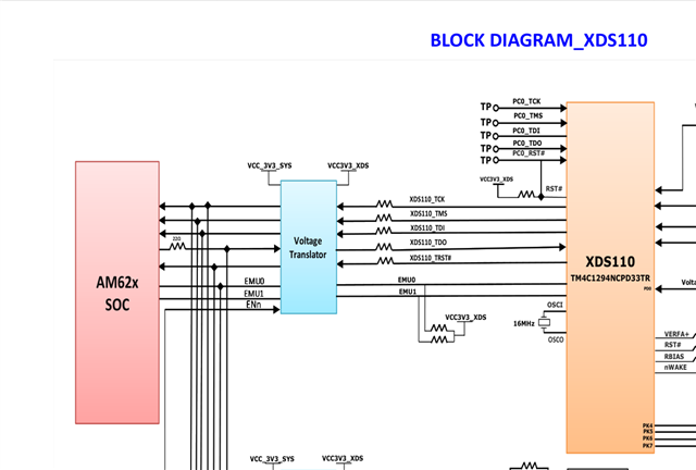
Any suggestion? Do we need to hook up more pins from the target? Should we do anything with the EMU[0] and [1] pins CCS highlights?
-----[Print the board config pathname(s)]------------------------------------
C:\Users\<snip>\AppData\Local\TEXASI~1\CCS\
ccs2050\0\0\BrdDat\testBoard.dat
-----[Print the reset-command software log-file]-----------------------------
This utility has selected a 100/110/510 class product.
This utility will load the adapter 'jioxds110.dll'.The library build date was 'Mar 4 2026'.
The library build time was '18:13:05'.
The library package version is '20.5.0.3902'.
The library component version is '35.35.0.0'.The controller does not use a programmable FPGA.
The controller has a version number of '5' (0x00000005).
The controller has an insertion length of '0' (0x00000000).This utility will attempt to reset the controller.
This utility has successfully reset the controller.
-----[Print the reset-command hardware log-file]-----------------------------
The scan-path will be reset by toggling the JTAG TRST signal.
The controller is the XDS110 with USB interface.
The link from controller to target is direct (without cable).
The software is configured for XDS110 features.
The controller cannot monitor the value on the EMU[0] pin.
The controller cannot monitor the value on the EMU[1] pin.
The controller cannot control the timing on output pins.
The controller cannot control the timing on input pins.
The scan-path link-delay has been set to exactly '0' (0x0000).
-----[An error has occurred and this utility has aborted]--------------------
This error is generated by TI's USCIF driver or utilities.
The value is '-233' (0xffffff17).
The title is 'SC_ERR_PATH_BROKEN'.
The explanation is:
The JTAG IR and DR scan-paths cannot circulate bits, they may be broken.
An attempt to scan the JTAG scan-path has failed.
The target's JTAG scan-path appears to be broken
with a stuck-at-ones or stuck-at-zero fault.