AM13E23019: MCPWM Interrupt Latency

Part Number: AM13E23019

Hello

I am observing interrupt latency of around 240ns (MCLK = 200MHz) . Below are the syconfig configuraitons 

Configurations
  • MCPWM4 Period is kept 16KHz (6249 Ticks), up count, No prescaler. MCPWM4 generate SyncOut pulse for eCAP when timebase counter equals to zero.
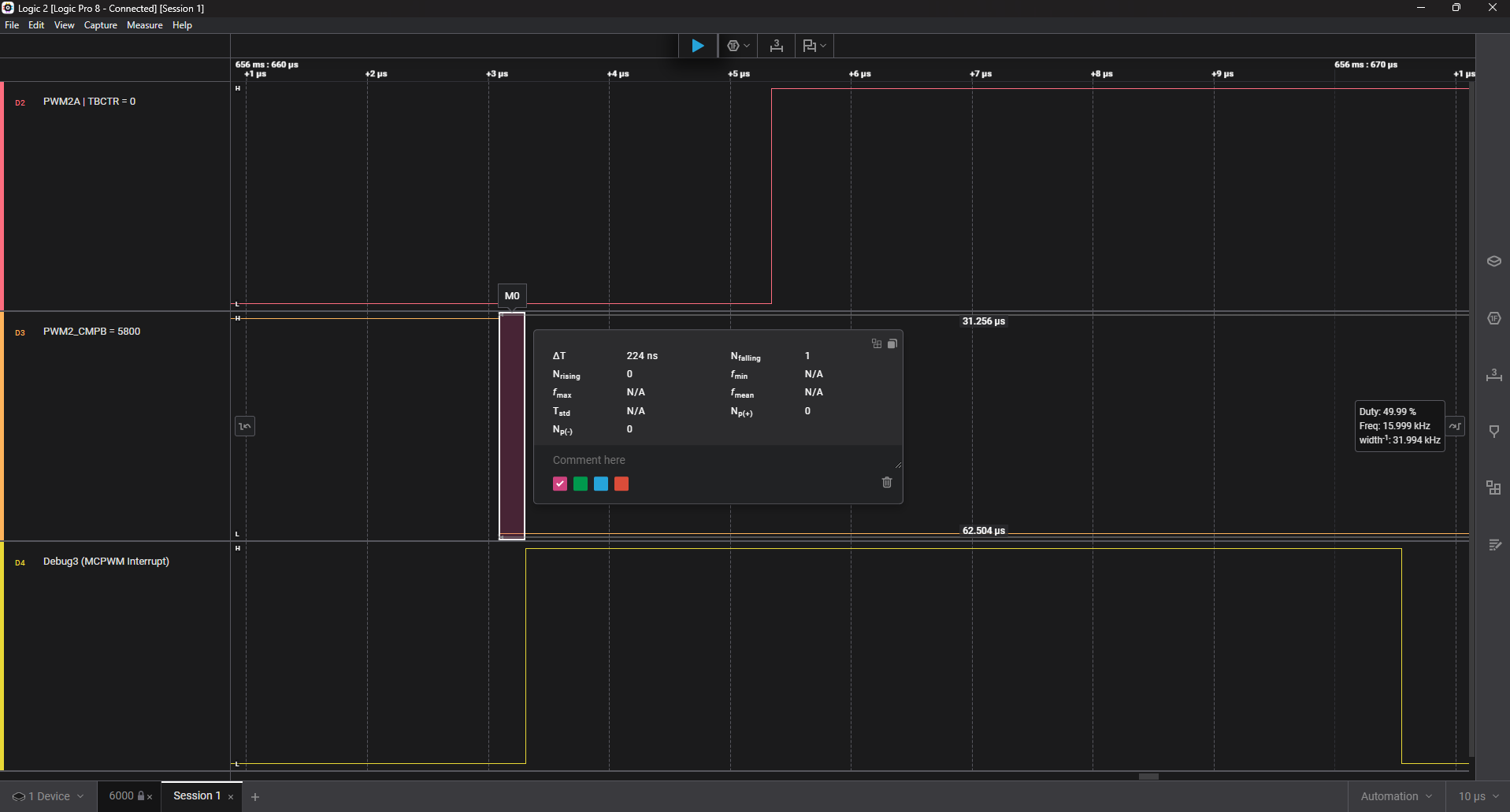
  • PWM2_CMPB = 5800 - this is used to generate accurate Pulse to verify the MCPWM interrupt latency
  • CMPC = 5800 - This is used to generate the MCPWM Interrupt(5800 is some random number. The goal is to generate the interrupt just before the time base counter becoming to zero)
  • PWM2A is configured to toggle When TBCTR = 0 
  • PWM2B is configured to toggle when TBCTR = PWM1_CMPB On Up Count 
  • ET1 : when the Time base counter is equal to CMPC, which is the same as PWM2_CMPB (5800). ET1 is configured as the source to generate interrupt
  • The priority of the MCPWM interrupt is kept the highest. Debug3 pin is toggled in ISR as first statement. 
extern "C" void APP_MCPWM_4_INT_Handler()
{
    BSP_AM13E230_E2::Debug3Pin_High();
    MotorControl_Callback();
    g_diagCounters.Mcpwm4++;
    DL_MCPWM_clearInterrupt(APP_MCPWM_4_INST, DL_MCPWM_INT_ET_1);
    DL_MCPWM_clearGlobalInterrupt(APP_MCPWM_4_INST);
    BSP_AM13E230_E2::Debug3Pin_Low();
}

void BSP_AM13E230_E2::Debug3Pin_High()
{
    DL_GPIO_setPins(GPIO_GRP_0_PIN_Debug3_PORT, GPIO_GRP_0_PIN_Debug3_PIN);
}
void BSP_AM13E230_E2::Debug3Pin_Low()
{
    DL_GPIO_clearPins(GPIO_GRP_0_PIN_Debug3_PORT, GPIO_GRP_0_PIN_Debug3_PIN);
}


Observation
  • There is interrupt latency observed (around 230ns) for MCPWM ISR. Please suggest if it can be improved or this is expected. image.png

    NOTE: Logic Analyser is configured to sample at 250 MHz


  • Hi Dheeraj,

    Thank you for the detailed post. The ~224-240 ns latency you are observing is higher than the theoretical minimum for the AM13E230x (Cortex-M33) and is most likely attributable to Flash execution overhead. Below is a breakdown of what is contributing to the latency and what can be done to reduce it.


    Expected Interrupt Latency Breakdown (Cortex-M33 @ 200 MHz)

    Component
    Cycles
    Time @ 200 MHz
    Peripheral interrupt recognition
    1-2
    5-10 ns
    Interrupt synchronization to CPU
    1-2
    5-10 ns
    Cortex-M33 HW context save (automatic)
    12
    60 ns
    Branch to ISR vector
    2
    10 ns
    Theoretical minimum (SRAM execution)
    ~17
    ~85 ns

    At 200 MHz, 240 ns equates to approximately 48 CPU cycles. The Cortex-M33 hardware minimum is ~12 cycles for context save alone, so the remaining overhead is most likely coming from Flash wait states if the ISR is executing from Flash.


    Primary Recommendation: Execute ISR from SRAM

    On the AM13E230x, Flash access at 200 MHz incurs wait states that directly add to observed latency once the CPU begins fetching ISR instructions. Placing the ISR in SRAM eliminates this overhead.

    In your linker file, define a SRAM region for time-critical functions:

    .ramfuncs : {
        *(.ramfuncs)
    } > SRAM

    Then place your ISR and any functions called directly within it into that section, with interrupt flags cleared at the top of the ISR:

    __attribute__((section(".ramfuncs")))
    extern "C" void APP_MCPWM_4_INT_Handler()
    {
        DL_MCPWM_clearInterrupt(APP_MCPWM_4_INST, DL_MCPWM_INT_ET_1);
        DL_MCPWM_clearGlobalInterrupt(APP_MCPWM_4_INST);
        BSP_AM13E230_E2::Debug3Pin_High();
        MotorControl_Callback();
        g_diagCounters.Mcpwm4++;
        BSP_AM13E230_E2::Debug3Pin_Low();
    }

    Clearing the interrupt flags at the top of the ISR rather than the end is recommended as general best practice. This allows the peripheral to re-arm for the next event immediately and avoids any possibility of a missed interrupt in back-to-back triggering scenarios.

    Also note that Debug3Pin_High, Debug3Pin_Low, and MotorControl_Callback should each be placed in SRAM as well. If any called function remains in Flash, you will still incur wait states on that fetch, which will be visible in your latency measurement since Debug3Pin_High is your first instrumented statement.


    Expected Results After Moving ISR to SRAM

    Configuration
    Estimated Latency
    ISR in Flash (current)
    ~220-240 ns
    ISR in SRAM, called functions remain in Flash
    ~120-150 ns
    ISR in SRAM, all called functions in SRAM
    ~85-100 ns
    Theoretical M33 minimum
    ~85 ns

    Measurement Note

    Your logic analyzer is sampling at 250 MHz, giving a resolution of 4 ns per sample. The reported latency carries an inherent uncertainty of approximately +/-4 ns, so the true value sits within a ~8 ns window around your measurement. This does not affect the diagnosis but is worth keeping in mind when validating the improvement after the SRAM change.


    Please give the SRAM placement a try and let us know what latency you observe afterward. If the latency remains higher than expected after that change, we can look further into NVIC priority configuration and any potential bus contention on the SRAM interface.

    Best Regards,

    Zackary Fleenor

  • Hi Zackary Fleenor

    Thanks for the detailed response. After making the Suggested changes I am able to achieve latency up to 125 ns. Here are the changes made. 

    1. Increasing optimisation to -O2 (MCPWM4 Interrupt does not happen on -O3 somehow)

    2. Shifting ISR into RAM 

    3. Shifting functions into RAM