AM263P4-Q1: SOC Does Not Reboot After PORz

Part Number: AM263P4-Q1
Other Parts Discussed in Thread: TPS6538600-Q1, AM263P4, SYSCONFIG

Hello,

We have custom HW with AM263P4 SOC, TPS6538600-Q1 PMIC and Infineon S25FL128LAGMFB013 Quad SPI flash.

The SBL and application boot and run fine in OSPI 4S mode (SOP_MODE_VALUE_VAL = 0000b) when applying power to the board.

I am developing the PMIC watchdog feature. When I deliberately break the watchdog trigger from SOC to PMIC, the PMIC correctly asserts NRST while keeping the 3V3 LDO on.

However, after NRST is deasserted, the SOC does not initiate loading the SBL and just sits there.
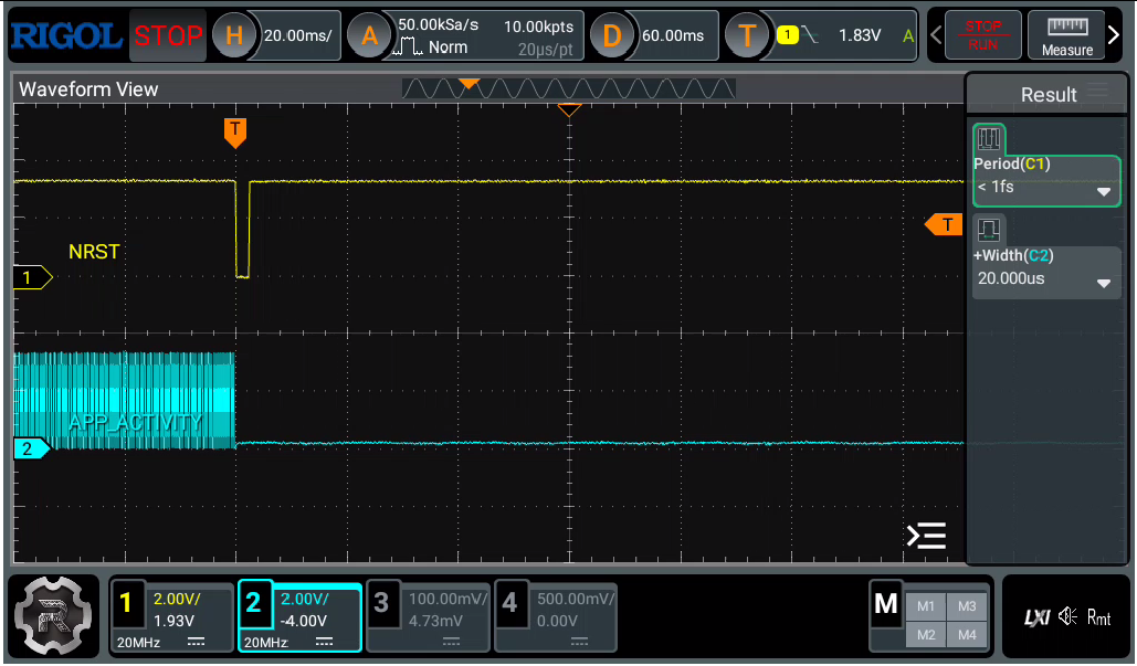
image.png

The flash connection is straightforward as follows:
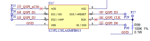
image.png

Why doesn't the RBL load the SBL when only PORz (NRST) is triggered please?

Thank you.

  • Hi Kier,

    Thank you for the query!!

    Can you please help me with the following details:

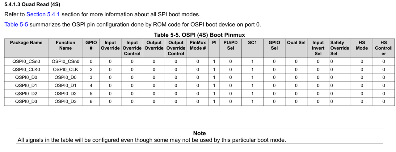
    1. Is the nCS, IO2, nRESET line pulled high with a weak pull up?
    2. Is the nRST connected to PORz release circuitry?
    3. Which version of SDK are you using?
    4. Are you setting the Flash in 3-byte addressing mode or in 4-byte addressing mode?

      Can you please share the schematic snippet of PORz release logic?

    Thanks & Regards,
    Rijohn

  • Hi Rijohn,

    Thanks for the quick reply.

    Is the nCS, IO2, nRESET line pulled high with a weak pull up?

    No, there are no external pullup resistors on these lines.

    Is the nRST connected to PORz release circuitry?

    No. We're not using the HW reset since the boot mode is QUAD.

    Which version of SDK are you using?

    SDK 10.2.0.15

    Are you setting the Flash in 3-byte addressing mode or in 4-byte addressing mode?

    In the FLASH configuration 4-byte is selected:

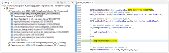
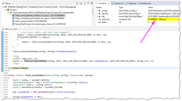
    But I checked this through debug and it's hitting the following line which looks like it's setting 3-byte.

    Note also in the screenshot above the code always assumes a OSPI_RESETPIN_DEDICATED. There's no way to select the other option: OSPI_RESETPIN_DQ3 which would be more appropriate for our device, even though we aren't using it because we use QUAD mode. Just an observation.

  • Hi Keir,

    Thank you for the quick response!!

    No, there are no external pullup resistors on these lines.

    It is recommended to have an external pull up on these lines. As MCU ROM does not enable the internal pull up on these lines by default.

    In the FLASH configuration 4-byte is selected:

    Disable the 4-byte addressing mode in SysConfig. Below is the reason:


    Let's keep the addressing mode fixed to 3-byte as our flash size is not greater than 128Mb 

    There's no way to select the other option: OSPI_RESETPIN_DQ3 which would be more appropriate for our device, even though we aren't using it because we use QUAD mode.

    Good Catch!! We need not have it in this case as there is no dedicated reset line. Comment OSPI_configResetPin API. Please comment it, save and rebuild the project.

    Thanks & Regards,
    Rijohn

  • Thank you.

    We'll have to park the pullup concern for the moment because I can't change that right now. Anyway, I'm not convinced this is the cause because the system works on power-on. If the pull-ups are correct at power on surely they are correct at PORz?

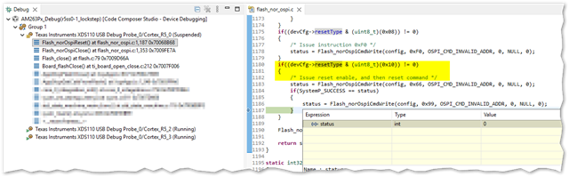
    In any case, I checked that a reset is issued when the flash driver closes after use.

    This should mean that as long as Flash_close() is called before the PORz, the flash IC should be in the same condition as a power-up shouldn't it?

  • BTW, I tried changing to 3 byte addressing but now my application can't write to flash and doesn't fix the issue anyway.

    However, there's no getting away from the fact that with a cold power on the RBL can read from the flash chip. If the RBL only supports 3 byte addressing then we can conclude the flash is successfully supporting both 3 and 4 byte addressing. This can't be the cause.

    I can only conclude that the Flash_norOspiReset() is not successful in returning the device to its power-on state.

  • Hi Kier,

    Can you please share here the example.sysconfig file of the SBL project.

    Yes, we might need to tweak the Flash_norOspiReset() for the case of this particular. I will check on this and get back to you.

    there's no getting away from the fact that with a cold power on the RBL can read from the flash chip. If the RBL only supports 3 byte addressing then we can conclude the flash is successfully supporting both 3 and 4 byte addressing.
    The RBL expects the flash to be in 3-byte addressing mode during QSPI boot mode (QSPI BOOTMODE = 0000). The reason I mentioned disabling 4-byte addressing mode is to handle potential reset scenarios. The ROM starts booting code from the beginning irrespective of whether the reset was a WARM or COLD reset. After RBL is done, if the SBL or application switches the flash to 4-byte addressing mode and a reset is triggered, the flash will remain stuck in 4-byte mode. Because there is no dedicated hardware reset line for the flash, there is no way to reset it alongside the MCU to ensure it reverts to 3-byte addressing mode for the ROM execution.
    Therefore, the safest approach is to never switch flashes smaller than or equal to 128Mb into 4-byte addressing mode, as a 3-byte address is sufficient to map the entire 128Mb memory density.
    Thanks & Regards,
    Rijohn
  • Hi Rijohn,

    Can you please share here the example.sysconfig file of the SBL project.

    Here's my syscfg file for the core0. I stripped out everything except OSPI and FLASH to protect IP. Let me know if some aspect is missing that you need.

    1667.Project.zip

    if the SBL or application switches the flash to 4-byte addressing mode and a reset is triggered, the flash will remain stuck in 4-byte mode

    Why do you think it gets stuck in 4 byte addressing mode after a reset?

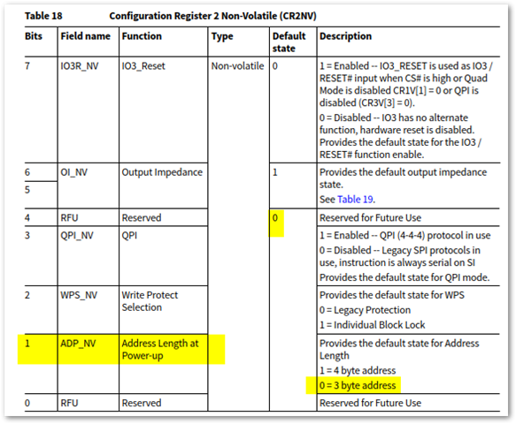
    The device has a non-volatile setting for address mode:

    Since RBL is able to talk to the flash after power on, we can conclude this must = 0, right? I will check its state after the reset command has been issued.

  • I added some code to read the contents of the CR2V register before and after reset.

    BEFORE Reset : Bit 0 is set indicating 4 byte addressing.

    AFTER Reset : Bit 0 is reset (default) indicating 3 byte addressing.

    So at the point of PORz from PMIC, the flash IC is in 3 byte address mode. I think evidence is mounting that this cannot be the cause for a lack of reboot.

  • Hi Kier,

    Can you please run the ospi_flash_diag example and share the console output?

    BEFORE Reset : Bit 0 is set indicating 4 byte addressing.

    Can you please disable the 4-byte addressing mode in sysconfig.

    Thanks & Regards,
    Rijohn

  • Hi Kier,

    BTW, I tried changing to 3 byte addressing but now my application can't write to flash and doesn't fix the issue anyway.

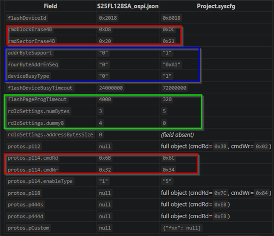
    I reviewed the SysConfig file and noticed that the read, write, and erase commands are currently configured for 4-byte addressing mode. We need to update these to commands compatible with 3-byte addressing mode.

    For example:

    Further Steps:

    1. Untick the "Enable 4-byte" in sysconfig (addrByteSupport = 0 , fourByteAddrEnSeq = 0 )
    2. Update the below to corresponding 3-byte address mode command as in column S25FL128SA_ospi.json.
      1. cmdBlockErase4B
      2. cmdSectorErase4B
      3. protos.p114.cmdRd
      4. protos.p114.cmdWr
      5. deviceBusyType
      6. flashDeviceBusyTimeout
      7. flashPageProgTimeout 

    3. Ensure that ospi /flash settings are used in both the SysConfig files of application and SBL.
    4. Save and rebuild the project

    Thanks & Regards,
    Rijohn

  • Hi Rijohn,

    Thank you I will try this but why do you think this will make a difference in theory? I have demonstrated that the device is in 3 byte address before a PORz.

    What if I had a device greater than 128Mb and I had no option but to use 4 byte addressing? Your answer suggests that it's impossible to use such a device with this SOC. Is that correct?

  • Hi Kier,

    BEFORE Reset : Bit 0 is set indicating 4 byte addressing.

    I see from your previous answer that BEFORE RESET flash is in 4-byte addressing mode. Sorry I am confused here.

    I have tested AM263Px + S25FL128 series of flash setting in 3-byte addressing mode. Please try updating the commands as mentioned in previous thread and let me know.

    What if I had a device greater than 128Mb and I had no option but to use 4 byte addressing? Your answer suggests that it's impossible to use such a device with this SOC. Is that correct?

    Yes, Current AM263Px ROM does not support flashes with only 4-byte addressing mode.


    Thanks, 
    Rijohn

  • Hi Rijohn,

    Please try updating the commands as mentioned in previous thread and let me know.

    Yes, I will try it, thank you.

    Yes, Current AM263Px ROM does not support flashes with only 4-byte addressing mode.

    That's not really the question I'm asking.

    This device supports both 3 AND 4 byte addressing. It successfully boots in 3 byte mode and I can successfully read and write in 4 byte mode in my application. If you force users to configure ONLY 3 byte mode, they cannot then use devices greater then 128Mb. Nowhere in the TRM or datasheet does it say you must use only 3 byte addressing for all conditions, it only says you must use 3 byte addresses at boot time. I have shown that I am using 3 byte addressing at boot time including when the PORz is asserted.

    If your proposal works for me, that's great. But your proposal puts a constraint on the flash device that is not present in the TRM as far as I can tell. Something doesn't add up.

  • Hi Kier,

    There is no generic constraint that prevents us from operating the flash in 4-byte addressing mode within the Secondary Bootloader (SBL) or the application. Most flash memories on the market power up in 3-byte addressing mode by default and then switch to 4-byte mode via a command. (However, I agree that certain Orderable Part Numbers (OPNs) do power up in 4-byte mode by default).
    The ROM expects the flash to be in 3-byte addressing mode. In this specific case, we are using a QSPI flash with a 128Mbit density and no dedicated reset line.
    If we intentionally switch to 4-byte addressing mode in the SBL or the application and a reset occurs—such as a Power-On Reset (PORz) or an intentional/unintentional warm reset—the flash will remain in 4-byte addressing mode. Consequently, the boot will fail because the ROM expects the flash to be in 3-byte addressing mode.
    Most flash memories with a density less than or equal to 128Mb do not have a dedicated reset line. If a dedicated reset line were available, this constraint would not exist. In the PCB hardware layout, the WARMRESETn pin would be routed as one of the reset sources for the flash reset pin. Therefore, if any reset occurs—whether a PORz or a warm reset (triggered intentionally or unintentionally by a voltage monitor error, watchdog timer, etc.)—the same signal resetting the MCU would simultaneously reset the flash. This ensures the flash returns to its default power-up state, which is 3-byte addressing mode. Hence satisfying ROM requirements. (Please refer to NOTE in Section 5.4.1 OSPI Boot in AM263Px TRM)
    In our current scenario, the flash density is 128Mbit, which is fully addressable using only 3-byte addressing mode; 4-byte addressing is unnecessary. Furthermore, because there is no dedicated reset line to the flash, the only reliable way to handle the addressing mode risk is to avoid switching to 4-byte mode entirely.
    For intentional software resets, you can call a flash API to switch back to 3-byte addressing mode right before triggering the warm reset. However, from a system perspective, we must also account for unintentional warm resets. This is why I propose the solution to never switch to 4-byte addressing mode in either the SBL or the application in current scenario.
    Summary
    • All SPI/QSPI/OSPI flash memories with densities above 128Mb must have a dedicated reset line for the reasons stated above.
    • The current AM263Px ROM does not support flash memories that operate exclusively in 4-byte addressing mode or those that power up in 4-byte addressing mode by default.
    Best regards,
    Rijohn
  • Hi Rijohn,

    Thank you very much. I made the 3-byte address changes* to SBL and Application. The latter can now write to flash but most importantly this solves the issue for me, the RBL now boots SBL.

    So it seems then that a software reset request ostensibly changes the addressing mode to 3-byte (CR2V.ADP and CR2V.ADS =0) but empirically it does not. There must be some other factor which means the flash device is not capable of talking to the RBL. Anyway, I'm going to quit while ahead and forget about it.

    *BTW, changing the deviceBusyType produces no change in the SysCfg code but it seems to work regardless.

  • Thank you for taking the time to write explanation and rationale.