AM2434: Trigger EnDat3 through external Interrupt via CAP

Part Number: AM2434

Hi,

is it possible to use EnDat3 in periodic-command code through triggering via an external interrupt the CAP-Input? I oriented myself on the routing example: 

https://e2e.ti.com/support/microcontrollers/arm-based-microcontrollers-group/arm-based-microcontrollers/f/arm-based-microcontrollers-forum/1452411/faq-lp-am243-routing-gpio-interrupts-to-pru-core

but i couldn't make it work.
Configuring Sciclient did work, but the PRU never registered an event.

Here the function i used:

int32_t routeGpio1ToIep0Cap0(uint16_t gpioPin)
{
    struct tisci_msg_rm_irq_set_req req;
    struct tisci_msg_rm_irq_set_resp resp;
    int32_t status;

    memset(&req, 0, sizeof(req));
    memset(&resp, 0, sizeof(resp));

    req.secondary_host = TISCI_MSG_VALUE_RM_UNUSED_SECONDARY_HOST;

    /*
     * GPIO0 source indexes 0...89 correspond to the individual
     * GPIO0 pin interrupt outputs.
     */
    req.src_id    = TISCI_DEV_GPIO1;
    req.src_index = gpioPin; // 6

    req.valid_params = TISCI_MSG_VALUE_RM_DST_ID_VALID | TISCI_MSG_VALUE_RM_DST_HOST_IRQ_VALID;

    /*
     * PRU_ICSSG0 destination inputs:
     *  4 = IEP0 CAP request 0
     *  5 = IEP0 CAP request 1
     *  ...
     *  9 = IEP0 CAP request 5
     */
    req.dst_id       = TISCI_DEV_PRU_ICSSG0; 
    req.dst_host_irq = 4;

    status = Sciclient_rmIrqSet(
        &req,
        &resp,
        SystemP_WAIT_FOREVER);

    return status;
}

LP-AM243x-Pin used: 48 (=PRG0_PRU0_GPO6/H2)
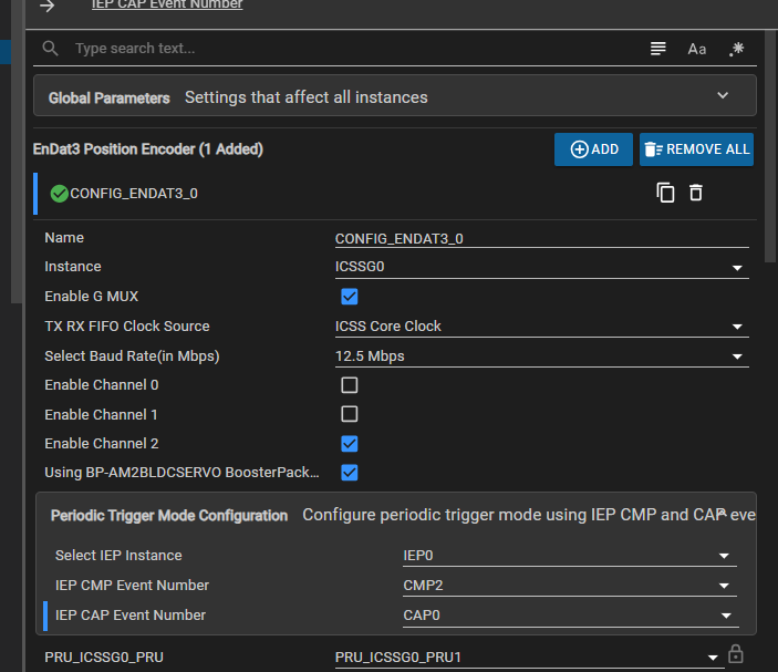
image.png

EnDat works with the IEP-Timer settings and CAP6.

Best regards,
Flo

  • Hy Flo,

    check the EnDat 2.2 example where CAP0 is used for Channel 1 with an external interrupt using the GPIO0_4 pin. Verify if any configuration is missing or incorrect.
    motor_control_sdk\examples\position_sense\endat_diagnostic\endat_periodic_trigger.c

    BR,

    Achala Ram

  • Hi Achala,

    i can't write to the register from the application. Reading is no problem. 
    Also do i need to configure the GPIO in a special way?

    Best regards,

    Flo

  • Hi Flo,

    we are checking on it and will get back to you.

    BR,

    Achala Ram

  • Hello,

    did you see the same error or could you tell me how to implement it?

    Best regards,

    Flo

  • Hi,

    We are working on the above issue. Please share you example.syscfg file with us.

    Also please tell, the GPIO pin which used to generate the interrupt/event, is it configured as GPIO or other functionality? Also is the functionality of GPIO pin changed during the runtime operation in your application code?

    Regards,

    Tushar

  • /**
     * These arguments were used when this file was generated. They will be automatically applied on subsequent loads
     * via the GUI or CLI. Run CLI with '--help' for additional information on how to override these arguments.
     * @cliArgs --device "AM243x_ALX_beta" --part "ALX" --package "ALX" --context "r5fss0-0" --product "MOTOR_CONTROL_SDK_AM243x@2025.00.00" --product "INDUSTRIAL_COMMUNICATIONS_SDK_AM243x@2025.00.00" --product "MCU_PLUS_SDK_AM243x@12.00.00"
     * @v2CliArgs --device "AM2434" --package "FCCSP (ALX)" --variant "AM2434-E" --context "r5fss0-0" --product "MOTOR_CONTROL_SDK_AM243x@2025.00.00" --product "INDUSTRIAL_COMMUNICATIONS_SDK_AM243x@2025.00.00" --product "MCU_PLUS_SDK_AM243x@12.00.00"
     * @versions {"tool":"1.27.0+4565"}
     */
    
    /**
     * Import the modules used in this configuration.
     */
    const gpio            = scripting.addModule("/drivers/gpio/gpio", {}, false);
    const gpio1           = gpio.addInstance();
    const pruicss         = scripting.addModule("/drivers/pruicss/pruicss", {}, false);
    const pruicss1        = pruicss.addInstance();
    const debug_log       = scripting.addModule("/kernel/dpl/debug_log");
    const dpl_cfg         = scripting.addModule("/kernel/dpl/dpl_cfg");
    const mpu_armv7       = scripting.addModule("/kernel/dpl/mpu_armv7", {}, false);
    const mpu_armv71      = mpu_armv7.addInstance();
    const mpu_armv72      = mpu_armv7.addInstance();
    const mpu_armv73      = mpu_armv7.addInstance();
    const mpu_armv74      = mpu_armv7.addInstance();
    const mpu_armv75      = mpu_armv7.addInstance();
    const default_linker  = scripting.addModule("/memory_configurator/default_linker", {}, false);
    const default_linker1 = default_linker.addInstance();
    const general         = scripting.addModule("/memory_configurator/general", {}, false);
    const general1        = general.addInstance();
    const region          = scripting.addModule("/memory_configurator/region", {}, false);
    const region1         = region.addInstance();
    const section         = scripting.addModule("/memory_configurator/section", {}, false);
    const section1        = section.addInstance();
    const section2        = section.addInstance();
    const section3        = section.addInstance();
    const section4        = section.addInstance();
    const section5        = section.addInstance();
    const section6        = section.addInstance();
    const section7        = section.addInstance();
    const section8        = section.addInstance();
    const section9        = section.addInstance();
    const section10       = section.addInstance();
    const section11       = section.addInstance();
    const endat3          = scripting.addModule("/position_sense/endat3", {}, false);
    const endat31         = endat3.addInstance();
    
    /**
     * Write custom configuration values to the imported modules.
     */
    gpio1.$name          = "CONFIG_GPIO_SYNC1_IN";
    gpio1.rx             = true;
    gpio1.trigType       = "RISE_EDGE";
    gpio1.GPIO_n.$assign = "PRG0_PRU0_GPO6";
    
    debug_log.enableUartLog        = true;
    debug_log.uartLog.$name        = "CONFIG_UART_CONSOLE";
    debug_log.uartLog.UART.$assign = "USART0";
    
    const uart_v0_template  = scripting.addModule("/drivers/uart/v0/uart_v0_template", {}, false);
    const uart_v0_template1 = uart_v0_template.addInstance({}, false);
    uart_v0_template1.$name = "drivers_uart_v0_uart_v0_template0";
    debug_log.uartLog.child = uart_v0_template1;
    
    mpu_armv71.$name             = "CONFIG_MPU_REGION0";
    mpu_armv71.size              = 31;
    mpu_armv71.attributes        = "Device";
    mpu_armv71.accessPermissions = "Supervisor RD+WR, User RD";
    mpu_armv71.allowExecute      = false;
    
    mpu_armv72.$name             = "CONFIG_MPU_REGION1";
    mpu_armv72.size              = 15;
    mpu_armv72.accessPermissions = "Supervisor RD+WR, User RD";
    
    mpu_armv73.$name             = "CONFIG_MPU_REGION2";
    mpu_armv73.baseAddr          = 0x41010000;
    mpu_armv73.size              = 15;
    mpu_armv73.accessPermissions = "Supervisor RD+WR, User RD";
    
    mpu_armv74.$name             = "CONFIG_MPU_REGION3";
    mpu_armv74.accessPermissions = "Supervisor RD+WR, User RD";
    mpu_armv74.baseAddr          = 0x70000000;
    mpu_armv74.size              = 21;
    
    mpu_armv75.$name             = "CONFIG_MPU_REGION4";
    mpu_armv75.baseAddr          = 0x60000000;
    mpu_armv75.size              = 28;
    mpu_armv75.accessPermissions = "Supervisor RD, User RD";
    
    default_linker1.$name = "memory_configurator_default_linker0";
    
    general1.$name        = "CONFIG_GENERAL0";
    general1.linker.$name = "TIARMCLANG0";
    
    region1.$name                               = "MEMORY_REGION_CONFIGURATION0";
    region1.memory_region.create(9);
    region1.memory_region[0].type               = "TCMA_R5F";
    region1.memory_region[0].$name              = "R5F_VECS";
    region1.memory_region[0].size               = 0x40;
    region1.memory_region[0].auto               = false;
    region1.memory_region[1].type               = "TCMA_R5F";
    region1.memory_region[1].$name              = "R5F_TCMA";
    region1.memory_region[1].size               = 0x7FC0;
    region1.memory_region[2].type               = "TCMB_R5F";
    region1.memory_region[2].$name              = "R5F_TCMB0";
    region1.memory_region[2].size               = 0x8000;
    region1.memory_region[3].$name              = "NON_CACHE_MEM";
    region1.memory_region[3].auto               = false;
    region1.memory_region[3].manualStartAddress = 0x70060000;
    region1.memory_region[3].size               = 0x8000;
    region1.memory_region[4].$name              = "MSRAM";
    region1.memory_region[4].auto               = false;
    region1.memory_region[4].manualStartAddress = 0x70080000;
    region1.memory_region[4].size               = 0x40000;
    region1.memory_region[5].type               = "FLASH";
    region1.memory_region[5].$name              = "FLASH";
    region1.memory_region[5].auto               = false;
    region1.memory_region[5].manualStartAddress = 0x60100000;
    region1.memory_region[5].size               = 0x80000;
    region1.memory_region[6].$name              = "USER_SHM_MEM";
    region1.memory_region[6].auto               = false;
    region1.memory_region[6].manualStartAddress = 0x701D0000;
    region1.memory_region[6].size               = 0x180;
    region1.memory_region[7].auto               = false;
    region1.memory_region[7].manualStartAddress = 0x701D0180;
    region1.memory_region[7].size               = 0x3E80;
    region1.memory_region[7].$name              = "LOG_SHM_MEM";
    region1.memory_region[8].auto               = false;
    region1.memory_region[8].manualStartAddress = 0x701D4000;
    region1.memory_region[8].size               = 0xC000;
    region1.memory_region[8].$name              = "RTOS_NORTOS_IPC_SHM_MEM";
    
    section1.$name                        = "Vector Table";
    section1.load_memory                  = "R5F_VECS";
    section1.group                        = false;
    section1.output_section.create(1);
    section1.output_section[0].$name      = ".vectors";
    section1.output_section[0].palignment = true;
    
    section2.$name                        = "Text Segments";
    section2.load_memory                  = "MSRAM";
    section2.output_section.create(5);
    section2.output_section[0].$name      = ".text.hwi";
    section2.output_section[0].palignment = true;
    section2.output_section[1].$name      = ".text.cache";
    section2.output_section[1].palignment = true;
    section2.output_section[2].$name      = ".text.mpu";
    section2.output_section[2].palignment = true;
    section2.output_section[3].$name      = ".text.boot";
    section2.output_section[3].palignment = true;
    section2.output_section[4].$name      = ".text:abort";
    section2.output_section[4].palignment = true;
    
    section3.$name                        = "Code and Read-Only Data";
    section3.load_memory                  = "MSRAM";
    section3.output_section.create(2);
    section3.output_section[0].$name      = ".text";
    section3.output_section[0].palignment = true;
    section3.output_section[1].$name      = ".rodata";
    section3.output_section[1].palignment = true;
    
    section4.$name                        = "Data Segment";
    section4.load_memory                  = "MSRAM";
    section4.output_section.create(1);
    section4.output_section[0].$name      = ".data";
    section4.output_section[0].palignment = true;
    
    section5.$name                                   = "Memory Segments";
    section5.load_memory                             = "MSRAM";
    section5.output_section.create(3);
    section5.output_section[0].$name                 = ".bss";
    section5.output_section[0].palignment            = true;
    section5.output_section[0].output_sections_start = "__BSS_START";
    section5.output_section[0].output_sections_end   = "__BSS_END";
    section5.output_section[1].$name                 = ".sysmem";
    section5.output_section[1].palignment            = true;
    section5.output_section[2].$name                 = ".stack";
    section5.output_section[2].palignment            = true;
    
    section6.$name                                    = "Stack Segments";
    section6.load_memory                              = "MSRAM";
    section6.output_section.create(5);
    section6.output_section[0].$name                  = ".irqstack";
    section6.output_section[0].output_sections_start  = "__IRQ_STACK_START";
    section6.output_section[0].output_sections_end    = "__IRQ_STACK_END";
    section6.output_section[0].input_section.create(1);
    section6.output_section[0].input_section[0].$name = ". = . + __IRQ_STACK_SIZE;";
    section6.output_section[1].$name                  = ".fiqstack";
    section6.output_section[1].output_sections_start  = "__FIQ_STACK_START";
    section6.output_section[1].output_sections_end    = "__FIQ_STACK_END";
    section6.output_section[1].input_section.create(1);
    section6.output_section[1].input_section[0].$name = ". = . + __FIQ_STACK_SIZE;";
    section6.output_section[2].$name                  = ".svcstack";
    section6.output_section[2].output_sections_start  = "__SVC_STACK_START";
    section6.output_section[2].output_sections_end    = "__SVC_STACK_END";
    section6.output_section[2].input_section.create(1);
    section6.output_section[2].input_section[0].$name = ". = . + __SVC_STACK_SIZE;";
    section6.output_section[3].$name                  = ".abortstack";
    section6.output_section[3].output_sections_start  = "__ABORT_STACK_START";
    section6.output_section[3].output_sections_end    = "__ABORT_STACK_END";
    section6.output_section[3].input_section.create(1);
    section6.output_section[3].input_section[0].$name = ". = . + __ABORT_STACK_SIZE;";
    section6.output_section[4].$name                  = ".undefinedstack";
    section6.output_section[4].output_sections_start  = "__UNDEFINED_STACK_START";
    section6.output_section[4].output_sections_end    = "__UNDEFINED_STACK_END";
    section6.output_section[4].input_section.create(1);
    section6.output_section[4].input_section[0].$name = ". = . + __UNDEFINED_STACK_SIZE;";
    
    section7.$name                        = "Initialization and Exception Handling";
    section7.load_memory                  = "MSRAM";
    section7.output_section.create(3);
    section7.output_section[0].$name      = ".ARM.exidx";
    section7.output_section[0].palignment = true;
    section7.output_section[1].$name      = ".init_array";
    section7.output_section[1].palignment = true;
    section7.output_section[2].$name      = ".fini_array";
    section7.output_section[2].palignment = true;
    
    section8.$name                       = "User Shared Memory";
    section8.type                        = "NOLOAD";
    section8.load_memory                 = "USER_SHM_MEM";
    section8.group                       = false;
    section8.output_section.create(1);
    section8.output_section[0].$name     = ".bss.user_shared_mem";
    section8.output_section[0].alignment = 0;
    
    section9.$name                       = "Log Shared Memory";
    section9.load_memory                 = "LOG_SHM_MEM";
    section9.type                        = "NOLOAD";
    section9.group                       = false;
    section9.output_section.create(1);
    section9.output_section[0].$name     = ".bss.log_shared_mem";
    section9.output_section[0].alignment = 0;
    
    section10.$name                       = "IPC Shared Memory";
    section10.type                        = "NOLOAD";
    section10.load_memory                 = "RTOS_NORTOS_IPC_SHM_MEM";
    section10.group                       = false;
    section10.output_section.create(1);
    section10.output_section[0].$name     = ".bss.ipc_vring_mem";
    section10.output_section[0].alignment = 0;
    
    section11.$name                       = "Non Cacheable Memory";
    section11.load_memory                 = "NON_CACHE_MEM";
    section11.group                       = false;
    section11.type                        = "NOLOAD";
    section11.output_section.create(1);
    section11.output_section[0].$name     = ".bss.nocache";
    section11.output_section[0].alignment = 0;
    
    endat31.$name                  = "CONFIG_ENDAT3_0";
    endat31.Booster_Pack           = true;
    endat31.G_MUX_EN               = true;
    endat31.channel_2              = true;
    endat31.channel_0              = false;
    endat31.CAP_Event_Num          = 0;
    endat31.ENC1_EN.$name          = "ENDAT3_0_BP_POWER_EN0";
    endat31.ENC1_EN.GPIO_n.$assign = "MMC1_SDCD";
    endat31.PRU_ICSSG0_PRU.$assign = "PRU_ICSSG0_PRU1";
    
    pruicss1.$name                           = "CONFIG_PRU_ICSS0";
    endat31.pru                              = pruicss1;
    pruicss1.coreClk                         = 300000000;
    pruicss1.AdditionalICSSSettings[0].$name = "CONFIG_PRU_ICSS_IO0";
    pruicss1.intcMapping.create(1);
    pruicss1.intcMapping[0].$name            = "CONFIG_ICSS0_INTC_MAPPING0";
    pruicss1.intcMapping[0].event            = "18";
    
    /**
     * Pinmux solution for unlocked pins/peripherals. This ensures that minor changes to the automatic solver in a future
     * version of the tool will not impact the pinmux you originally saw.  These lines can be completely deleted in order to
     * re-solve from scratch.
     */
    debug_log.uartLog.UART.RXD.$suggestSolution   = "UART0_RXD";
    debug_log.uartLog.UART.TXD.$suggestSolution   = "UART0_TXD";
    endat31.PRU_ICSSG0_PRU.GPO8.$suggestSolution  = "PRG0_PRU1_GPO8";
    endat31.PRU_ICSSG0_PRU.GPO12.$suggestSolution = "PRG0_PRU1_GPO12";
    endat31.PRU_ICSSG0_PRU.GPO6.$suggestSolution  = "PRG0_PRU1_GPO6";
    endat31.PRU_ICSSG0_PRU.GPI11.$suggestSolution = "PRG0_PRU1_GPO11";
    

    Hi,

    it's configured as GPIO, as you see in the syscfg., i don't change anything during runtime operation. The first Problem is, i can't even write to the routing register, without generating an error. 

    Regards,

    Flo

  • Hi Flo,

    it's configured as GPIO, as you see in the syscfg., i don't change anything during runtime operation. The first Problem is, i can't even write to the routing register, without generating an error. 

    Direct writing is protected for GPIOMUX router registers. You can only configure these using the sciclient API. For that, you need to perform all the steps mentioned here, including board configuration and resource allocation: [FAQ] LP-AM243: Routing GPIO interrupts to PRU core.

    On the PRU side, you also need to enable the external event for the CAP0 event.

    You need to configure bit[18] of the IEP_CAP_CFG_REG register. See the register details in the TRM: 14.3.6.1.25 PRU_IEP_IEP Registers.

    These configurations are required to get EnDat3 in periodic-command mode through triggering via an external interrupt on the CAP input:

    1. Configure the MUX router and GPIO as described here: [FAQ] LP-AM243: Routing GPIO interrupts to PRU core.
    2. In the EnDat3 example, select a CAP0-CAP5 event as the IEP CAP Event Number for periodic mode.
    3. Enable the external event for the configured CAP event in bits [18-23] of the IEP_CAP_CFG_REG register.

    Once you complete all the above-mentioned configurations, the MUX router register and IEP CAP register should be configured as shown below:

    1)MUX router register, Offset 0x4c for CAP0:

    • bit[16]: Router enable bit.
    • bit[0-7]: Index number of the selected GPIO pin (e.g., B4 for PRG0_PRU0_GPO4/K2).

    2)IEP CAP Register: offset 0x18 is for IEP_CAP_CFG_REG register. enabled bit[18] for the external event. 

    Note: Other IEP register configurations, including CAP event enable, are handled by the EnDat application when the CAP mode periodic command is executed.

    BR,
    Achala Ram