Part Number: LP-MSPM0G3519
Other Parts Discussed in Thread: MSPM0G1518, LP-MSPM0G3507, SYSCONFIG, MSPM0G3519
Hello,
the issue described in the following was already mentioned in this thread (https://e2e.ti.com/support/microcontrollers/arm-based-microcontrollers-group/arm-based-microcontrollers/f/arm-based-microcontrollers-forum/1673781/mspm0g1518-synchronized-adc-sampling-issue-mspm0g1518-mspm0g1507-lp-mspm0g3519/6453952)
But since it is not the main issue being discussed there I thought it is worth to give it a own thread.
In our project were using the MSPM0G1518 and for development the LP-MSPM0G3519.
Due to the implementation of a safety library we observed major stability issues of the ADC0 instance compared to ADC1.
Setup
In our reduced test project ADC0 and ADC1 convert 2 channels sequentially each:
- Supply monitor with reference VREF, 15µs sample time
- Supply monitor with reference VDDA, 15µs sample time
The conversion is started every 100µs within an ISR handling a SYSTICK interrupt. No other peripherals are configured. All unused pins are set to output low.
The issue was reproduced using LP-MSPM0G3519 and multiple custom boards using MSPM0G1518.
Detail
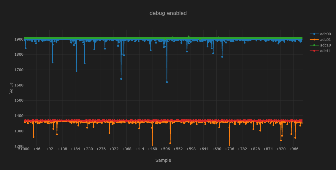
In the following are some graphs showing the conversion results over 100ms. The ADC results are read in the ISR before restarting the ADCs.
adc00: ADC0 memres0, adc10: ADC1 memres0, ...

As it can be seen in the graph ADC1 results are very stable whereas the ADC0 results are much mor unstable with high dips.
- Even without starting ADC1, the results of ADC0 still look bad.
- Reducing the CPU clock to 32MHz or less did not changed anything.
- Changing ADC0 clock source to SYSOSC instead of ULPCLK does not help either.
To double check we migrated the project to use a LP-MSPM0G3507:

Here all measurments a as stable as expected.
Can someone confirm this issue and maybe provide a explanation/ solution?
Thanks in advance.
Attachements:
Code:
main.c:
#include "ti_msp_dl_config.h"


volatile uint16_t adc00[1000u];
volatile uint16_t adc01[1000u];
volatile uint16_t adc10[1000u];
volatile uint16_t adc11[1000u];
volatile uint16_t     i;


/**
 * @brief Handle interrupts triggered by TIMER_SWTICK
 * @details
 *
 */
void SysTick_Handler( void ) {
  adc00[i] = DL_ADC12_getMemResult( ADC0_INST, DL_ADC12_MEM_IDX_0 );
  adc01[i] = DL_ADC12_getMemResult( ADC0_INST, DL_ADC12_MEM_IDX_1 );
  adc10[i] = DL_ADC12_getMemResult( ADC1_INST, DL_ADC12_MEM_IDX_0 );
  adc11[i] = DL_ADC12_getMemResult( ADC1_INST, DL_ADC12_MEM_IDX_1 );
  i++;

  if ( 1000 <= i ) {
    i = 0;
  }

  /* Enable and start ADC conversion */
  DL_ADC12_enableConversions( ADC0_INST );
  DL_ADC12_enableConversions( ADC1_INST );
  DL_ADC12_startConversion( ADC0_INST );
  DL_ADC12_startConversion( ADC1_INST);
}


int main(void)
{
    SYSCFG_DL_init();

    while (1) {
        __WFI();
    }
}
sysconfig:
/**
 * AI AGENTS: Do not edit this file directly. There is no validation or error feedback when
 * editing manually — mistakes will be silent until the file is loaded in SysConfig.
 * Use the SysConfig MCP server instead to make changes with immediate error reporting.
 *
 * These arguments were used when this file was generated. They will be automatically applied on subsequent loads
 * via the GUI or CLI. Run CLI with '--help' for additional information on how to override these arguments.
 * @cliArgs --device "MSPM0G351X" --part "Default" --package "LQFP-100(PZ)" --product "mspm0_sdk@2.11.00.07"
 * @v2CliArgs --device "MSPM0G3519" --package "LQFP-100(PZ)" --product "mspm0_sdk@2.11.00.07"
 * @versions {"tool":"1.28.0+4712"}
 */

/**
 * Import the modules used in this configuration.
 */
const ADC12   = scripting.addModule("/ti/driverlib/ADC12", {}, false);
const ADC121  = ADC12.addInstance();
const ADC122  = ADC12.addInstance();
const Board   = scripting.addModule("/ti/driverlib/Board");
const SYSCTL  = scripting.addModule("/ti/driverlib/SYSCTL");
const SYSTICK = scripting.addModule("/ti/driverlib/SYSTICK");
const VREF    = scripting.addModule("/ti/driverlib/VREF");

/**
 * Write custom configuration values to the imported modules.
 */
const divider7       = system.clockTree["PLL_PDIV"];
divider7.divideValue = 8;

const divider9       = system.clockTree["UDIV"];
divider9.divideValue = 2;

const gate8  = system.clockTree["MFPCLKGATE"];
gate8.enable = true;

const multiplier2         = system.clockTree["PLL_QDIV"];
multiplier2.multiplyValue = 39;

const mux8       = system.clockTree["HSCLKMUX"];
mux8.inputSelect = "HSCLKMUX_SYSPLL0";

const mux12                                     = system.clockTree["SYSPLLMUX"];
mux12.overrideworkaroundFCCPeriod_SYSPLL_ERR_01 = true;
mux12.workaroundFCCPeriod_SYSPLL_ERR_01         = 32;

const oscillator2           = system.clockTree["SYSOSC"];
oscillator2.enableSYSOSCFCL = true;

ADC121.$name                 = "ADC0";
ADC121.samplingOperationMode = "sequence";
ADC121.adcMem0_name          = "U_SUPPLY_VREF_0";
ADC121.adcMem0chansel        = "DL_ADC12_INPUT_CHAN_15";
ADC121.adcMem0vref           = "VREF";
ADC121.adcMem0vrefp          = "INTREF";
ADC121.adcMem1_name          = "U_SUPPLY_VDDA_0";
ADC121.adcMem1chansel        = "DL_ADC12_INPUT_CHAN_15";
ADC121.adcMem2_name          = "U_SUPPLY_VREF_1";
ADC121.adcMem2chansel        = "DL_ADC12_INPUT_CHAN_15";
ADC121.adcMem2vref           = "VREF";
ADC121.adcMem2vrefp          = "INTREF";
ADC121.adcMem3_name          = "U_SUPPLY_VDDA_1";
ADC121.adcMem3chansel        = "DL_ADC12_INPUT_CHAN_15";
ADC121.adcMem4_name          = "U_SUPPLY_VREF_2";
ADC121.adcMem4chansel        = "DL_ADC12_INPUT_CHAN_15";
ADC121.adcMem4vref           = "VREF";
ADC121.adcMem4vrefp          = "INTREF";
ADC121.adcMem5_name          = "U_SUPPLY_VDDA_2";
ADC121.adcMem5chansel        = "DL_ADC12_INPUT_CHAN_15";
ADC121.adcMem6_name          = "U_SUPPLY_VREF_3";
ADC121.adcMem6chansel        = "DL_ADC12_INPUT_CHAN_15";
ADC121.adcMem6vref           = "VREF";
ADC121.adcMem6vrefp          = "INTREF";
ADC121.adcMem7_name          = "U_SUPPLY_VDDA3";
ADC121.adcMem7chansel        = "DL_ADC12_INPUT_CHAN_15";
ADC121.adcMem8_name          = "U_SUPPLY_VREF_4";
ADC121.adcMem8chansel        = "DL_ADC12_INPUT_CHAN_15";
ADC121.adcMem8vref           = "VREF";
ADC121.adcMem8vrefp          = "INTREF";
ADC121.adcMem9_name          = "U_SUPPLY_VDDA_4";
ADC121.adcMem9chansel        = "DL_ADC12_INPUT_CHAN_15";
ADC121.adcMem2stime          = "DL_ADC12_SAMPLE_TIMER_SOURCE_SCOMP1";
ADC121.adcMem3stime          = "DL_ADC12_SAMPLE_TIMER_SOURCE_SCOMP1";
ADC121.adcMem4stime          = "DL_ADC12_SAMPLE_TIMER_SOURCE_SCOMP1";
ADC121.adcMem5stime          = "DL_ADC12_SAMPLE_TIMER_SOURCE_SCOMP1";
ADC121.adcMem6stime          = "DL_ADC12_SAMPLE_TIMER_SOURCE_SCOMP1";
ADC121.adcMem7stime          = "DL_ADC12_SAMPLE_TIMER_SOURCE_SCOMP1";
ADC121.adcMem8stime          = "DL_ADC12_SAMPLE_TIMER_SOURCE_SCOMP1";
ADC121.adcMem9stime          = "DL_ADC12_SAMPLE_TIMER_SOURCE_SCOMP1";
ADC121.enableFIFO            = true;
ADC121.sampCnt               = 1;
ADC121.enabledDMATriggers    = ["DL_ADC12_DMA_MEM1_RESULT_LOADED","DL_ADC12_DMA_MEM3_RESULT_LOADED","DL_ADC12_DMA_MEM5_RESULT_LOADED","DL_ADC12_DMA_MEM7_RESULT_LOADED","DL_ADC12_DMA_MEM9_RESULT_LOADED"];
ADC121.sampleTime0           = "15us";
ADC121.sampleTime1           = "5us";
ADC121.sampClkSrc            = "DL_ADC12_CLOCK_ULPCLK";
ADC121.endAdd                = 1;
ADC121.peripheral.$assign    = "ADC0";

ADC122.$name                 = "ADC1";
ADC122.samplingOperationMode = "sequence";
ADC122.adcMem0_name          = "U_SUPPLY_VREF_0";
ADC122.adcMem0chansel        = "DL_ADC12_INPUT_CHAN_15";
ADC122.adcMem0vref           = "VREF";
ADC122.adcMem0vrefp          = "INTREF";
ADC122.adcMem1_name          = "U_SUPPLY_VDDA_0";
ADC122.adcMem1chansel        = "DL_ADC12_INPUT_CHAN_15";
ADC122.adcMem2_name          = "U_SUPPLY_VREF_1";
ADC122.adcMem2chansel        = "DL_ADC12_INPUT_CHAN_15";
ADC122.adcMem2vref           = "VREF";
ADC122.adcMem2vrefp          = "INTREF";
ADC122.adcMem3_name          = "U_SUPPLY_VDDA_1";
ADC122.adcMem3chansel        = "DL_ADC12_INPUT_CHAN_15";
ADC122.adcMem4_name          = "U_SUPPLY_VREF_2";
ADC122.adcMem4chansel        = "DL_ADC12_INPUT_CHAN_15";
ADC122.adcMem4vref           = "VREF";
ADC122.adcMem4vrefp          = "INTREF";
ADC122.adcMem5_name          = "U_SUPPLY_VDDA_2";
ADC122.adcMem5chansel        = "DL_ADC12_INPUT_CHAN_15";
ADC122.adcMem6_name          = "U_SUPPLY_VREF_3";
ADC122.adcMem6chansel        = "DL_ADC12_INPUT_CHAN_15";
ADC122.adcMem6vref           = "VREF";
ADC122.adcMem6vrefp          = "INTREF";
ADC122.adcMem7_name          = "U_SUPPLY_VDDA3";
ADC122.adcMem7chansel        = "DL_ADC12_INPUT_CHAN_15";
ADC122.adcMem8_name          = "U_SUPPLY_VREF_4";
ADC122.adcMem8chansel        = "DL_ADC12_INPUT_CHAN_15";
ADC122.adcMem8vref           = "VREF";
ADC122.adcMem8vrefp          = "INTREF";
ADC122.adcMem9_name          = "U_SUPPLY_VDDA_4";
ADC122.adcMem9chansel        = "DL_ADC12_INPUT_CHAN_15";
ADC122.adcMem2stime          = "DL_ADC12_SAMPLE_TIMER_SOURCE_SCOMP1";
ADC122.adcMem3stime          = "DL_ADC12_SAMPLE_TIMER_SOURCE_SCOMP1";
ADC122.adcMem4stime          = "DL_ADC12_SAMPLE_TIMER_SOURCE_SCOMP1";
ADC122.adcMem5stime          = "DL_ADC12_SAMPLE_TIMER_SOURCE_SCOMP1";
ADC122.adcMem6stime          = "DL_ADC12_SAMPLE_TIMER_SOURCE_SCOMP1";
ADC122.adcMem7stime          = "DL_ADC12_SAMPLE_TIMER_SOURCE_SCOMP1";
ADC122.adcMem8stime          = "DL_ADC12_SAMPLE_TIMER_SOURCE_SCOMP1";
ADC122.adcMem9stime          = "DL_ADC12_SAMPLE_TIMER_SOURCE_SCOMP1";
ADC122.enableFIFO            = true;
ADC122.sampCnt               = 1;
ADC122.enabledDMATriggers    = ["DL_ADC12_DMA_MEM1_RESULT_LOADED","DL_ADC12_DMA_MEM3_RESULT_LOADED","DL_ADC12_DMA_MEM5_RESULT_LOADED","DL_ADC12_DMA_MEM7_RESULT_LOADED","DL_ADC12_DMA_MEM9_RESULT_LOADED"];
ADC122.sampleTime0           = "15us";
ADC122.sampleTime1           = "5us";
ADC122.sampClkSrc            = "DL_ADC12_CLOCK_ULPCLK";
ADC122.endAdd                = 1;
ADC122.peripheral.$assign    = "ADC1";

Board.configureUnused = true;

SYSCTL.clockTreeEn       = true;
SYSCTL.validateClkStatus = true;

SYSTICK.periodEnable    = true;
SYSTICK.period          = 7800;
SYSTICK.interruptEnable = true;
SYSTICK.systickEnable   = true;

VREF.basicIntVolt       = "DL_VREF_BUFCONFIG_OUTPUT_2_5V";
VREF.checkVREFReady     = true;
VREF.basicExtVolt       = 2.5;
VREF.peripheral.$assign = "VREF";

/**
 * Pinmux solution for unlocked pins/peripherals. This ensures that minor changes to the automatic solver in a future
 * version of the tool will not impact the pinmux you originally saw.  These lines can be completely deleted in order to
 * re-solve from scratch.
 */
Board.peripheral.$suggestSolution          = "DEBUGSS";
Board.peripheral.swclkPin.$suggestSolution = "PA20";
Board.peripheral.swdioPin.$suggestSolution = "PA19";