This thread has been locked.

If you have a related question, please click the "Ask a related question" button in the top right corner. The newly created question will be automatically linked to this question.

uart problem in lm4f233h5qc

Other Parts Discussed in Thread: MAX3232, MAX232

Hi...i'm using our own data logger which has LM4F232H5QC with 8mhz crystal..i'm checking the uart communiation using uart 7.n i'm using tera term terminal ..i'm using sample code of stellaries controller.but i'm not able to get see anything on tera term terminal .Please help me if i would have done any mistake..

int
main(void)
{
tContext sContext;
tRectangle sRect;

//
// Enable lazy stacking for interrupt handlers. This allows floating-point
// instructions to be used within interrupt handlers, but at the expense of
// extra stack usage.
//
ROM_FPULazyStackingEnable();

//
// Set the clocking to run directly from the crystal.
//
ROM_SysCtlClockSet(SYSCTL_SYSDIV_1 | SYSCTL_USE_OSC | SYSCTL_OSC_MAIN |
SYSCTL_XTAL_8MHZ);

//
// Initialize the UART.
//
ROM_SysCtlPeripheralEnable(SYSCTL_PERIPH_GPIOE);
ROM_GPIOPinConfigure(GPIO_PE0_U7RX);
ROM_GPIOPinConfigure(GPIO_PE1_U7TX);
ROM_GPIOPinTypeUART(GPIO_PORTE_BASE, GPIO_PIN_0 | GPIO_PIN_1);
UARTStdioInit(0);

UARTprintf("Hello, world!\n");

//
// Initialize the display driver.
//
CFAL96x64x16Init();

//
// Initialize the graphics context.
//
GrContextInit(&sContext, &g_sCFAL96x64x16);

//
// Fill the top 24 rows of the screen with blue to create the banner.
//
sRect.sXMin = 0;
sRect.sYMin = 0;
sRect.sXMax = GrContextDpyWidthGet(&sContext) - 1;
sRect.sYMax = 23;
GrContextForegroundSet(&sContext, ClrDarkBlue);
GrRectFill(&sContext, &sRect);

//
// Put a white box around the banner.
//
GrContextForegroundSet(&sContext, ClrWhite);
GrRectDraw(&sContext, &sRect);

//
// Put the application name in the middle of the banner.
//
GrContextFontSet(&sContext, g_pFontCm12);
GrStringDrawCentered(&sContext, "hello", -1,
GrContextDpyWidthGet(&sContext) / 2, 10, 0);

//
// Say hello using the Computer Modern 40 point font.
//
GrContextFontSet(&sContext, g_pFontCm12/*g_pFontFixed6x8*/);
GrStringDrawCentered(&sContext, "Hello World!", -1,
GrContextDpyWidthGet(&sContext) / 2,
((GrContextDpyHeightGet(&sContext) - 24) / 2) + 24,
0);

//
// Flush any cached drawing operations.
//
GrFlush(&sContext);

//
// We are finished. Hang around doing nothing.
//
while(1)
{
}
}

  • Hello Rashmi,

    Please check the function call for UARTStdioInit. It would not accept UART-7 as an input and neither would UARTprintf.

    Also do check that the pins from UART-7 (in this case PE0 and PE1) is connected to the Com Ports to PC.

    Regards

    Amit

  • Rashmi yc said:
    UARTStdioInit(0);

    This enables UART0 not UART7. From what I know, you are only able to enable UART0-2 using UARTStdioInit. I recommend using non-uartstdio C API.

    Try UARTConfigSetExpClk(). See details at the Tivaware Peripheral Library Users Guide.

    -kel

  • Nice job, Kel!  (but for steering Stellaris (4F232) user to rebrandware - StellarisWare works swell - avoids/escapes multiple issues which (unfortunately) inflict the rebrand...)

    As always - posters left to their own devices - fail to fully/properly describe their method of connecting to their remote PC!  As this happens (so often) as to be predictable - this can be reduced to a, "Communication Area - typical failure diagnostic."

    When using an MCU's UART which is not connected via ICDI (or similar) - users must properly "mate" that UART to their remote UART.  (usually a PC)  Special care/attention must be paid to signal levels - RS232 levels will likely harm any MCU if not properly conditioned/level shifted...

  • Hi..Thank you for your reply.

    now i have modified the program but still not getting answer...please help me

    void RS232Init(unsigned long );
    int
    main(void)
    {

    ROM_FPULazyStackingEnable();
    //
    // Set the clocking to run directly from the crystal.
    //
    ROM_SysCtlClockSet(SYSCTL_SYSDIV_1 | SYSCTL_USE_OSC | SYSCTL_OSC_MAIN |
    SYSCTL_XTAL_8MHZ);
    RS232Init(115200);
    UARTprintf("***Project Name : Data Logger***\n");

    while(1);


    }

    void RS232Init(unsigned long ulBaudRate)
    {
    //
    // Enable the peripherals used by this example.
    //
    ROM_SysCtlPeripheralEnable(SYSCTL_PERIPH_GPIOE);
    ROM_SysCtlPeripheralEnable(SYSCTL_PERIPH_UART7);

    //
    // Set GPIO E0 and E1 as UART pins.
    //
    ROM_GPIOPinConfigure(GPIO_PE0_U7RX);
    ROM_GPIOPinConfigure(GPIO_PE1_U7TX);
    ROM_GPIOPinTypeUART(GPIO_PORTE_BASE, GPIO_PIN_0 | GPIO_PIN_1);
    ROM_GPIOPadConfigSet(GPIO_PORTE_BASE, GPIO_PIN_0 | GPIO_PIN_1,
    GPIO_STRENGTH_4MA, GPIO_PIN_TYPE_STD_WPU);
    //
    // Configure the UART for 115,200, 8-N-1 operation.
    //
    // ROM_UARTConfigSetExpClk(UART7_BASE, ROM_SysCtlClockGet(), ulBaudRate,
    // (UART_CONFIG_WLEN_8 | UART_CONFIG_STOP_ONE |
    // UART_CONFIG_PAR_NONE));

    UARTStdioInitExpClk(7,ulBaudRate);

    }

  • Hello Rashmi,

    Did you check the UARTStdioInitExpClk function. It calls UARTStdioConfig which has a UART Map table that will not allow UART7. I would suggest you do a simple UART Initialization using functions in UARTStdioConfig and changing base address for UART7.

    Then instead of using UARTprintf, use UARTCharPut to trasnmit on U7TX pin. Without understanding the function nesting and the manner in which the same is used, it would be a never ending post.

    Regards

    Amit

  • Hi..sorry i didn't go through death into uart  peripheral ..now i have modified the program..but i'm not getting the output..


    int main(void)
    {
    SysCtlClockSet(SYSCTL_SYSDIV_1 | SYSCTL_USE_OSC| SYSCTL_OSC_MAIN | SYSCTL_XTAL_8MHZ);

    SysCtlPeripheralEnable(SYSCTL_PERIPH_UART7);
    SysCtlPeripheralEnable(SYSCTL_PERIPH_GPIOE);
    GPIOPinConfigure(GPIO_PE0_U7RX);
    GPIOPinConfigure(GPIO_PE1_U7TX);
    GPIOPinTypeUART(GPIO_PORTE_BASE, GPIO_PIN_0 | GPIO_PIN_1);

    UARTConfigSetExpClk(UART7_BASE, SysCtlClockGet(), 115200,(UART_CONFIG_WLEN_8 | UART_CONFIG_STOP_ONE | UART_CONFIG_PAR_NONE));
    UARTEnable(UART7_BASE);

    UARTCharPut(UART7_BASE, 'E');
    UARTCharPut(UART7_BASE, 'n');
    UARTCharPut(UART7_BASE, 't');
    UARTCharPut(UART7_BASE, 'e');
    UARTCharPut(UART7_BASE, 'r');
    UARTCharPut(UART7_BASE, ' ');
    UARTCharPut(UART7_BASE, 'T');
    UARTCharPut(UART7_BASE, 'e');
    UARTCharPut(UART7_BASE, 'x');
    UARTCharPut(UART7_BASE, 't');
    UARTCharPut(UART7_BASE, ':');
    UARTCharPut(UART7_BASE, ' ');
    while (1)
    {
    if (UARTCharsAvail(UART7_BASE)) UARTCharPut(UART7_BASE, UARTCharGet(UART7_BASE));
    }

    }

  • Hi,

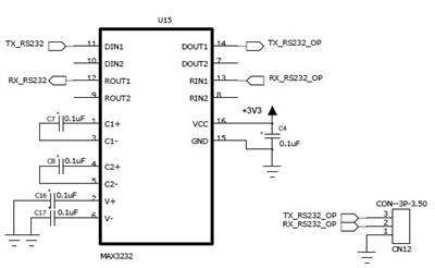
    If you need to connect to PC, then a level converter like MAX3232 is needed between your board and PC. 

    Otherwise does not work. UART0 has a special treatment - it is transferred throu ICDI and USB.

    Petrei

  • Hi...i have connected MAX3232 between controller n pc..i'm taking the output of  MAX3232 to pc..

  • Hello Rashmi,

    Did you check on the scope that the UART TX Pin from TM4C is toggling. Similarly in the o/p of MAX3232. If yes, then please check that the UART Port is correctly setup (port number, baud rate, stop bits, parity) in the UART Application (I am not sure if you are using HuperTerm, TTerm or puTTY...)

    If possible post the snapshot from a scope as mentioned above.

    Regards

    Amit

  • Hi sorry for late reply...i'm cheking the Tx and Rx pins in oscilloscope..but i'm not able see any pulses in oscilloscope...please help me.

  • Hi,

       Post a schematic diagram showing connections from microcontroller UART to MAX232 to PC.

    - kel

  • Hi Rashimi,

         I assume the OP prefix at your signals refers to your PC connection. Should be like this below. Where did you tap the oscilloscope?

         TX_RS232 -> DIN1   - - - - -   DOUT1-> RX_RS32_OP

         RX_RS232 <- ROUT1   - - - - -   RIN1<-TRX_RS32_OP 

         Also, your capacitor value too small 0.1uF??? The MAX232 I have used before had 10uF drum capacitor across C1+ and C-. Same with C2+ and C-.

    - kel

  • I'm checking  DOUT1-> RX_RS32_OP and RIN1<-TRX_RS32_OP at CN12 connector.You mean to say i need replace from  0.uf to 10 uf???

  • Long ago - the original RS232 level shifters did require such (relatively) high value, electrolytic caps.  But most all now work quite well w/ 0.1uF - yielding great cost/size saving.  And indeed - poster's chip is modern - needs not those huge,expensive caps.

    As poster states there is no recognizable output from UART_TX - troubleshooting "down the line" (i.e. RS232 level shifter) seems inappropriate - at this time!

    Poster should follow Amit's advice to use more basic "UARTCharPut" function.  Insure all earlier, different functions have been removed.

    Further - it may help to try another UART (temporarily) simply to test/verify the code set-up/execution.  Many are available - you just need to verify UART_TX to get started.

  • Hi...what i can do now??i'm not able to find the answer ..

  • Simple-minded solution suggestion "n"...

    Temporarily change UART_TX pin from UART to simple, push-pull, GPIO Output. Then program it to go high.  Confirm via either an Led or your scope.  (such will determine if the pin is "able" to go high - and that you're probing the correct pin - and that the pin is not unfairly/unduly "loaded" etc.)

    Basics - KISS - this thread is way too long for so basic an objective...

  • We've a similar MCU (smaller, LX4F231) and our Uart code is nearly identical - and works across all Uart Ports - our custom board.

    Only thing I see of possible significance: you immediately call UARTCharPut() after you UARTEnable(). 

    UARTEnable(UART7_BASE);

    UARTCharPut(UART7_BASE, 'E');

    In our code - we employ Uart_Init as a unique function - which forces some delay between the enabling of the Uart and its follow on access.  So - suggest that you insert a second (or so) of known delay prior to UARTCharPut().

    Again - your updated code listing - after you complied w/Amit's direction (UARTCharPut()) is nearly line by line equal to ours - which has long worked well on a very similar LX4F MCU...  (on > 1K delivered boards)

  • Hi..Now  i added these two lines.

    GPIOPinTypeGPIOOutput(GPIO_PORTE_BASE, GPIO_PIN_1); 
    GPIOPinWrite(GPIO_PORTE_BASE,GPIO_PIN_1,0x02);

    I have seen in oscilloscope.but it is not going to high..

  • Hello Rashmi

    Reducing the code to the following

    ROM_SysCtlClockSet(SYSCTL_SYSDIV_1 | SYSCTL_USE_OSC | SYSCTL_OSC_MAIN |
    SYSCTL_XTAL_8MHZ); //
    // Initialize the UART.
    //
    ROM_SysCtlPeripheralEnable(SYSCTL_PERIPH_GPIOE);
    GPIOPinTypeGPIOOutput(GPIO_PORTE_BASE, GPIO_PIN_1); 

    while(1) {
    GPIOPinWrite(GPIO_PORTE_BASE,GPIO_PIN_1,GPIO_PIN_1);

    GPIOPinWrite(GPIO_PORTE_BASE,GPIO_PIN_1,0x00);

    }

    Do you see a clock type signal on the scope? If yes, then the port IO is fine. If not then I would suggest checking the same on another IO or checking the schematic of the design to see the right probe point is being viewed

    Regards

    Amit

  • Appears that latest suggestion, "roots/hopes" that toggle of defiant gpio will force it into submission.  (I doubt that)

    As I past advised - and now seconded by factory - positively insure that you are probing the correct pin!  Probe very carefully - right at that MCU pin.  (i.e. NOT at some, "easier to probe header, or via, etc.)

    You seem, "bound/determined" to use only that pin.  Have not Amit, several others, worked long/hard enough in your behalf so that you can switch to another UART and test/verify?

    Have you a 2nd board?  If so - have you repeated this adventure there?

    Your post's subject/title lists LM4X233 - yet your initial post conflicts- listing LM4X232 - which is it?  As I recall the 232 was a large MCU.  We employ LX4F231 which does not support that "high" a UART.  Perhaps the 233 (if that's really what you use) is similarly pin/port limited/challenged...

    We can see/accept that earlier (pre-RS232 level shifter addition) you may have damaged UART7_RX - but hard to imagine how UART7_TX could be so victimized.  (unless - by mistake - you hooked the level shifter's output to the MCU rather than your PC!  We have seen clients - under time pressure - do that.  {but only once!})  Hiding such facts from this tech-jury does your helpers no favor - wastes a valuable resource. 

    Suggest that with power off - you employ a "proper" DMM in resistance mode - and measure the resistance between PE1 and ground.  Present that measurement to us.  (proper DMM will limit test voltage to < 5V to protect the tested device)

    One more point - follow Amit's last post which "holds" your code w/in that while loop - so that other program code cannot "undo" the setup of PE1 as an output.  Amit's code will run that gpio at its fastest speed - insertion of a delay between the output's order "high" - and then "low" - will enable even a DMM to record the far slower, output toggling.

  • Hi...i'm getting pulses..can you please check with the schematic what i have sent you.because now if i enter character then it is display the diffreent symbol..y so??

  • Hello Rashmi

    Did you check that the Baud Rate at both LM4F device and PC are identical along with the configuration of parity, number of bits, Stop bit and LSB/MSB first topology.

    Best thing is to measure the start time of a UART transaction where the LSB is 1, to ensure that the correct baud is being generated by LM4F232.

    Regards

    Amit

  • Rashmi yc said:
    i'm getting pulses

    Might you share here w/your long suffering "helpers" just how you managed to, "get pulses?"

    Mismatched characters usually result from mismatch between baud rate, number of data or stop bits, or parity.  Have you checked each?  (really?)

  • Baud Rate = 115200(both lm4f n pc)

     parity = none

    number of bits = 8 bit

    Stop bit = 1

    but i'm not able to see LSB/MSB first topology. in teraterm terminal


  • Thanks for that.  You've made no effort to describe "HOW" you got PE1 to finally output!  Don't you feel that you owe that to your helpers?  (we surely do!)  You must think of the many others who may encounter similar - "hoarding" your method or fix benefits no one!!!

    You are "self-diagnosing" by "unable to see LSB/MSB topology."  8 bits should resolve unless you're set to wider character set @ your terminal.

    Instead - send just a few characters.  Suggest A B C from the MCU - then tell us what the terminal reads.

    Also - slow down the baud rate (at both MCU and terminal) just in case 115K proves too fast.  9600 is easier for both the MCU and terminal program/PC to resolve.  Again MATCH the MCU settings to your terminal settings.

    And do tell us HOW you got PE1 to output.

  • Hello Rashmi,

    Absolutely agree with cb1 on the last statement. Having users posting back "how they got it to work" is a very useful information for others when they are looking at a same/similar issue. In some of the Past threads, we have asked users to post the code or solution and it has proved useful (twice in my recollection).

    As for LSB-MSB, send a known character like A, look it up the ASCII table for the 8-bit hex code and see which bits come out first. LM4F sends LSB bit so if character "A" is 0x41 then the bit stream will look as 10000010. If the PC application sees it the other way then it would be read as 0x82 which would be ","

    Regards

    Amit

  • Hi....i got output because of  schematic problem i was not getting the output..now i suppose to print the string like 

    UARTprintf("***Software Rev : 0***\n");    but it not printing on hyper terminal

  • Maddening.  Twice poster's been asked to send a "controlled character" and then report results as viewed upon PC Terminal.

    Yet twice - such direction has been rejected.   And - in most recent, "enlightenment" we're told, "Not printing!"  (I'd shoot myself - if my errant schematic or probing did not prevent...)

    Move over, "Don't work" you've got a new (equally profound/useless) ally.

  • Hello Rashmi

    Debugging a non-working system involves breaking the problem into smaller conditions to check. Ask yourself the question, "If the Laptop does not boot, then do you still try to open Internet Explorer, or do you check for the battery and charger working first"

    So break down the problem as

    1. Is the UART TX pin at the TM4C123 toggling and toggling as per a simple character?

    2. Is it toggling at the output of the MAX232 device?

    3. Is it toggling at the other end of the Cable connected to the PC?

    4. Did you try checking if the device manger in the PC is detecting a serial port?

    Regards

    Amit