This thread has been locked.

If you have a related question, please click the "Ask a related question" button in the top right corner. The newly created question will be automatically linked to this question.

TM4C123 GXL I2C CONFIG AND I2CM_DRV - L3GD20H - LSM303D USE

Other Parts Discussed in Thread: TM4C123GH6PM

Hello, I'm using tiva c series prototiping board, and pololu minIMU V. 3.0 with L3GD20H - LSM303D sensors, communicating to I2C0 Bus, I'm using sensorlib drivers in code but this alwais go to HardFault_Handler, i'm using Keil uvision 5.12 and TivaWare_C_Series-2.1.0.12573 libraries, mi code its divided in tre steps, first task code, second general driver (in this use tivaware functions) and third tivaware drivers,

code for mi task

__task void Posicion(void){
	
	//Inicializacion del canal de datos I2C
	CNFG_I2CM_Init();
	
	//Inicializacion del sensor de Giroscopio
	//L3GD20H_Init();
	
	//Inicializacion del sensor de Acelerometro y Magnetometro
	LSM303D_Init();
	
	while(1){
		while(velocista.ctrl_sys1 != 0){
			
			//Lectura de datos de los sensores de posicion
			L3GD20H_Gyr_Read(&velocista.Pos_Gyro[0], &velocista.Pos_Gyro[1], &velocista.Pos_Gyro[2]);
			LSM303D_Acc_Read(&velocista.Pos_Accel[0], &velocista.Pos_Accel[1], &velocista.Pos_Accel[2]);
			LSM303D_Mag_Read(&velocista.Pos_Mag[0], &velocista.Pos_Mag[1], &velocista.Pos_Mag[2]);
						
			//Pausa del sistema
			os_dly_wait (2);
			}
		//Pausa del sistema
		os_dly_wait (2);
		}
	}

this is the code for my driver, this is based in sensorlib user guide

#include "rtl.h"
#include "stdbool.h"
#include "stdint.h"
#include "TM4C123GH6PM.h"
#include "hw_memmap.h"
#include "i2cm_drv.h"
#include "lsm303d.h"
#include "l3gd20h.h"
#include "hw_l3gd20h.h"
#include "hw_lsm303d.h"
#include "sysctl.h"
#include "i2c.h"


/*--------------------------------------------------------------------------------
// Funciones requeridas para el funcionamiento del puerto I2C
--------------------------------------------------------------------------------*/

// The I2C master driver instance data.
tI2CMInstance g_sI2CMSimpleInst;

// A boolean that is set when an I2C transaction is completed.
volatile bool g_bI2CMSimpleDone = true;

// The interrupt handler for the I2C module.
void I2CMSimpleIntHandler(void){

	// Call the I2C master driver interrupt handler.
	I2CMIntHandler(&g_sI2CMSimpleInst);	
	}

// The function that is provided by this example as a callback when I2C
// transactions have completed.

void I2CMSimpleCallback(void *pvData, uint_fast8_t ui8Status){

	// See if an error occurred.
	if(ui8Status != I2CM_STATUS_SUCCESS){

		// An error occurred, so handle it here if required.
		}

	// Indicate that the I2C transaction has completed.
	g_bI2CMSimpleDone = true;
	}


/*--------------------------------------------------------------------------------
Funcion 1 'CNFG_I2CM_Init' Configuracion de transmision por puerto I2C
--------------------------------------------------------------------------------*/
void CNFG_I2CM_Init(void){
	
	// The I2C master driver instance data.
	tI2CMInstance g_sI2CMSimpleInst;
	
	// A boolean that is set when an I2C transaction is completed.
	//volatile bool g_bI2CMSimpleDone = true;
	
	// Set the clocking to run directly from the external crystal/oscillator.
	// TODO: The SYSCTL_XTAL_ value must be changed to match the value of the
	// crystal on your board.
	SysCtlClockSet(SYSCTL_SYSDIV_10 | SYSCTL_USE_PLL | SYSCTL_OSC_MAIN |
								SYSCTL_XTAL_16MHZ);

	// Enable and initialize the I2C0 master module.  Use the system clock for
	// the I2C0 module.     // I2C data transfer rate set to 400kbps.
	I2CMasterInitExpClk(I2C0_BASE, SysCtlClockGet(), true); 
	
	//clear I2C FIFOs
  //HWREG(I2C0_BASE + I2C_O_FIFOCTL) = 80008000;
	
	// Initialize the I2C master driver. It is assumed that the I2C module has
	// already been enabled and the I2C pins have been configured.
	I2CMInit(&g_sI2CMSimpleInst, I2C0_BASE, INT_I2C0, 0xff, 0xff, 120000000);
	
}

///*--------------------------------------------------------------------------------
//Funciones requeridas para el funcionamiento del sensor L3GD20H
//--------------------------------------------------------------------------------*/
// A boolean that is set when a L3GD20H command has completed.
volatile bool g_bl3gd20hDone;

// The function that is provided by this example as a callback when L3GD20H
// transactions have completed.

void l3gd20hCallback(void *pvCallbackData, uint_fast8_t ui8Status){

	// See if an error occurred.
	if(ui8Status != I2CM_STATUS_SUCCESS){
	// An error occurred, so handle it here if required.
		}
	
	// Indicate that the L3GD20H transaction has completed.
	g_bl3gd20hDone = true;
	}

///*--------------------------------------------------------------------------------
//Funcion 2 'L3GD20H_Init' Iniciaizacion del Giroscopio L3GD20H
//--------------------------------------------------------------------------------*/
void L3GD20H_Init(void){ 
	
	//float fGyro[3];
	tI2CMInstance sI2CInst;
	tL3GD20H sl3gd20h;

	// Initialize the L3GD20H. This code assumes that the I2C master instance
	// has already been initialized.
	g_bl3gd20hDone = false;
	L3GD20HInit(&sl3gd20h, &sI2CInst, 0x68, l3gd20hCallback, 0);
	while(!g_bl3gd20hDone){
		}

	// Configure the L3GD20H for 500 deg/sec sensitivity
	g_bl3gd20hDone = false;
	L3GD20HReadModifyWrite(&sl3gd20h, L3GD20H_O_CTRL4, ~L3GD20H_CTRL4_FS_M, L3GD20H_CTRL4_FS_500DPS, l3gd20hCallback,	0);
	while(!g_bl3gd20hDone){
		}
}

/*--------------------------------------------------------------------------------
Funcion 3 'L3GD20H_Read' Lectura de datos del Giroscopio L3GD20H
*--------------------------------------------------------------------------------*/
void L3GD20H_Gyr_Read(float* fGyro_X, float* fGyro_Y, float* fGyro_Z){
	
	// A boolean that is set when a L3GD20H command has completed.
	volatile bool g_bl3gd20hDone;
	
	float fGyro[3];
	tL3GD20H sl3gd20h;
	
	// Request another reading from the L3GD20H.
	g_bl3gd20hDone = false;
	L3GD20HDataRead(&sl3gd20h, l3gd20hCallback, 0);
	while(!g_bl3gd20hDone){
		}
	
	// Get the new gyroscope readings.
	L3GD20HDataGyroGetFloat(&sl3gd20h, &fGyro[0], &fGyro[1], &fGyro[2]);
	
	// Return Gyroscope values in poiter 
	*fGyro_X = fGyro[0];
	*fGyro_Y = fGyro[1];
	*fGyro_Z = fGyro[2];
	}

/*--------------------------------------------------------------------------------
Funciones requeridas para el funcionamiento del sensor LSM303D
--------------------------------------------------------------------------------*/

// A boolean that is set when a LSM303D command has completed.
volatile bool g_bLSM303DDone;

// The function that is provided by this example as a callback when LSM303D
// transactions have completed.
void LSM303DCallback(void *pvCallbackData, uint_fast8_t ui8Status){

	// See if an error occurred.
	if(ui8Status != I2CM_STATUS_SUCCESS){
	// An error occurred, so handle it here if required.
		}
	
	// Indicate that the LSM303D transaction has completed.
	g_bLSM303DDone = true;
	}

/*--------------------------------------------------------------------------------
Funcion 4 'LSM303D_Init' Iniciaizacion del Acelerometro y Magnetometro LSM303D
--------------------------------------------------------------------------------*/
void LSM303D_Init(void){ 
	
	// A boolean that is set when a LSM303D command has completed.
	volatile bool g_bLSM303DDone;
	
	tI2CMInstance sI2CInst;
	tLSM303D sLSM303D;

	// Initialize the LSM303D. This code assumes that the I2C master instance
	// has already been initialized.
	g_bLSM303DDone = false;
	LSM303DInit(&sLSM303D, &sI2CInst, 0x68, LSM303DCallback, 0);
	while(!g_bLSM303DDone){
		}

	// Configure the LSM303D for +/- 4 g accelerometer range.
	g_bLSM303DDone = false;
	LSM303DReadModifyWrite(&sLSM303D, LSM303D_O_CTRL2,~LSM303D_CTRL2_AFS_M,	LSM303D_CTRL2_AFS_4G, LSM303DCallback,0);
	while(!g_bLSM303DDone){
		}
}

/*--------------------------------------------------------------------------------
Funcion 3 'LSM303D_Acc_Read' Lectura de datos del Acelerometro LSM303D
*--------------------------------------------------------------------------------*/
void LSM303D_Acc_Read(float* fAccel_X, float* fAccel_Y, float* fAccel_Z){
	
	// A boolean that is set when a LSM303D command has completed.
	volatile bool g_bLSM303DDone;
	
	float fAccel[3];
	tLSM303D sLSM303D;
	
	// Request another reading from the LSM303D.
	g_bLSM303DDone = false;
	LSM303DDataRead(&sLSM303D, LSM303DCallback, 0);
	while(!g_bLSM303DDone){
		}

	// Get the new accelerometer readings.
	LSM303DDataAccelGetFloat(&sLSM303D, &fAccel[0], &fAccel[1], &fAccel[2]);
	
	// Return accelerometer values in poiter 
	*fAccel_X = fAccel[0];
	*fAccel_Y = fAccel[1];
	*fAccel_Z = fAccel[2];
	
}

/*--------------------------------------------------------------------------------
Funcion 4 'LSM303D_Mag_Read' Lectura de datos del Magnetometro LSM303D
*--------------------------------------------------------------------------------*/
void LSM303D_Mag_Read(float* fMag_X, float* fMag_Y, float* fMag_Z){
	
	// A boolean that is set when a LSM303D command has completed.
	volatile bool g_bLSM303DDone;
	
	float fMag[3];
	tLSM303D sLSM303D;
	
	// Request another reading from the LSM303D.
	g_bLSM303DDone = false;
	LSM303DDataRead(&sLSM303D, LSM303DCallback, 0);
	while(!g_bLSM303DDone){
		}
	
	// Get the new magnetometer readings.
	LSM303DDataMagnetoGetFloat(&sLSM303D, &fMag[0], &fMag[1], &fMag[2]);
	//
	
	// Return accelerometer values in poiter 
	*fMag_X = fMag[0];
	*fMag_Y = fMag[1];
	*fMag_Z = fMag[2];
	
}

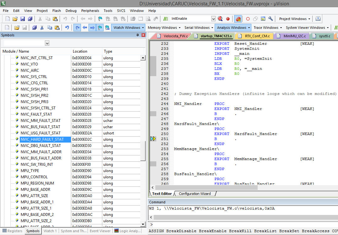
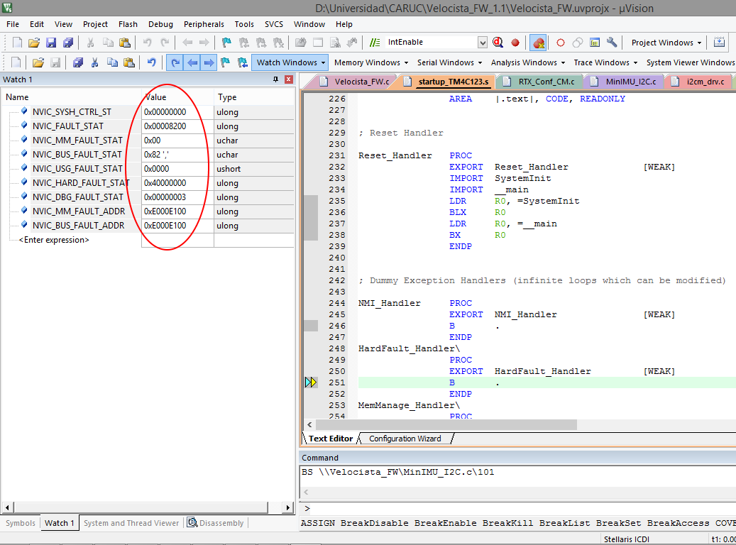
finali in debug i'm detect the code that generate the hardfault esception

in line:

I2CMInit(&g_sI2CMSimpleInst, I2C0_BASE, INT_I2C0, 0xff, 0xff, 120000000);

function go to enable interrupt in file i2cm_drv.c

MAP_IntEnable(ui8Int);

and finaly execute this code in interrupt.c

        //
        // Enable the general interrupt.
        //
        HWREG(g_pui32EnRegs[(ui32Interrupt - 16) / 32]) =
            1 << ((ui32Interrupt - 16) & 31);

and go to hardfault exception

and the rebuild not generate errors


Thanks  for your help !!

  • Hi Raul, value of fault register are necessary to completely diagnose fault, first sticky notes on this forum address the frequent cause of fault and malfunctioning, try read them and if persist publish fault register as explained on that post.
    I don't see I2C init code of GPIO if not external from before to launch RTOS task can be the main cause of HWFault. are you using TM4C129 series? If not 120MHz are excessive so lower the clock too.
  • Hi Roberto, thanks for your reply, sorry for not explain i2c init code, this is post in PortFunctionInit(); generate whith tiva c series pin mux utility in init task, all de tasks used gpio, pwm, qei, adc, uart, use this function for gpio config in task init, all funcion ok but the I2C not.

    In EXPORT HardFault_Handler it's equial to 0x000004B6 i dont see if this value its a fault register.

    I'm use Tiva C TM4C123GXL, the 120 MHz it's copy paste error : ), i'm change for 80 MHz but the error persist.
  • Hi, check all point of this post:
    e2e.ti.com/.../374640
    check issue 2 for I2C and issue 6 for Fault and register we need see.
    If you ported code from 129 to 123 read also the part I added in reply to Amit analysis.
  • Hello Raul,

    May be I am tired but in the code I do not see SysCtlPeripheralEnable call for enabling the clock to the I2C Module!!!

    Regards
    Amit
  • Hello Amit,

    the GPIO pins and periperials enable it's generated at init of RTX-OS in my project, the code is:

     int main (void) {
    
      SystemCoreClockUpdate();
    
      os_sys_init (init);                   /* Initialize RTX and start init     */
    }
    
    __task void init(void){
    	
    	PortFunctionInit();								  							/* Inicializar Pines          	*/
    	
    	//Configuracion de las variables de control
    	velocista.vel_max = 110;
    	velocista.vel_min = 90;
    	velocista.rev_max = -100;
    	velocista.kp = 40;
    	velocista.kd = 260;
    	velocista.ki = 0;
    	velocista.t_mues = 1;
    	
    	//Inicializacion de tareas
    	t_Posicion = os_tsk_create (Posicion, 0);					/* start task 'Posicion'				*/
    	t_Ctrl_L_B = os_tsk_create (Ctrl_L_B, 0);					/* start task 'Ctrl_L_B' 			  */
    		
      //Eliminacion de la tarea de inicio
    	os_tsk_delete_self();
    }

    the function PortFunctionInit() its generate for Tiva C Series Pin Mux and Contain this code:

    void
    PortFunctionInit(void)
    {
        // Enable Peripheral Clocks
        MAP_SysCtlPeripheralEnable(SYSCTL_PERIPH_PWM0);
        MAP_SysCtlPeripheralEnable(SYSCTL_PERIPH_QEI0);
        MAP_SysCtlPeripheralEnable(SYSCTL_PERIPH_PWM1);
        MAP_SysCtlPeripheralEnable(SYSCTL_PERIPH_ADC0);
        MAP_SysCtlPeripheralEnable(SYSCTL_PERIPH_UART1);
        MAP_SysCtlPeripheralEnable(SYSCTL_PERIPH_I2C0);
        MAP_SysCtlPeripheralEnable(SYSCTL_PERIPH_QEI1);
        MAP_SysCtlPeripheralEnable(SYSCTL_PERIPH_GPIOA);
        MAP_SysCtlPeripheralEnable(SYSCTL_PERIPH_GPIOB);
        MAP_SysCtlPeripheralEnable(SYSCTL_PERIPH_GPIOC);
        MAP_SysCtlPeripheralEnable(SYSCTL_PERIPH_GPIOD);
        MAP_SysCtlPeripheralEnable(SYSCTL_PERIPH_GPIOE);
            MAP_SysCtlPeripheralEnable(SYSCTL_PERIPH_GPIOF);

        // Enable pin PE4 for ADC AIN9
        MAP_GPIOPinTypeADC(GPIO_PORTE_BASE, GPIO_PIN_4);
        
        // Enable pin PE5 for ADC AIN8
        MAP_GPIOPinTypeADC(GPIO_PORTE_BASE, GPIO_PIN_5);
            
        // Enable pin PE3 for ADC AIN0
        MAP_GPIOPinTypeADC(GPIO_PORTE_BASE, GPIO_PIN_3);
            
        // Enable pin PE2 for ADC AIN1
        MAP_GPIOPinTypeADC(GPIO_PORTE_BASE, GPIO_PIN_2);

        // Enable pin PE1 for ADC AIN2
        MAP_GPIOPinTypeADC(GPIO_PORTE_BASE, GPIO_PIN_1);

        // Enable pin PD3 for ADC AIN4
        MAP_GPIOPinTypeADC(GPIO_PORTD_BASE, GPIO_PIN_3);
            
        // Enable pin PD2 for ADC AIN5
        MAP_GPIOPinTypeADC(GPIO_PORTD_BASE, GPIO_PIN_2);

        // Enable pin PD1 for ADC AIN6
        MAP_GPIOPinTypeADC(GPIO_PORTD_BASE, GPIO_PIN_1);
            
            // Enable pin PD0 for ADC AIN7
        MAP_GPIOPinTypeADC(GPIO_PORTD_BASE, GPIO_PIN_0);

        // Enable pin PB3 for I2C0 I2C0SDA
        MAP_GPIOPinConfigure(GPIO_PB3_I2C0SDA);
        MAP_GPIOPinTypeI2C(GPIO_PORTB_BASE, GPIO_PIN_3);

        // Enable pin PB2 for I2C0 I2C0SCL
        MAP_GPIOPinConfigure(GPIO_PB2_I2C0SCL);
        MAP_GPIOPinTypeI2CSCL(GPIO_PORTB_BASE, GPIO_PIN_2);

        // Enable pin PB6 for PWM0 M0PWM0
        MAP_GPIOPinConfigure(GPIO_PB6_M0PWM0);
        MAP_GPIOPinTypePWM(GPIO_PORTB_BASE, GPIO_PIN_6);

        // Enable pin PB7 for PWM0 M0PWM1
        MAP_GPIOPinConfigure(GPIO_PB7_M0PWM1);
        MAP_GPIOPinTypePWM(GPIO_PORTB_BASE, GPIO_PIN_7);

        // Enable pin PA6 for PWM1 M1PWM2
        MAP_GPIOPinConfigure(GPIO_PA6_M1PWM2);
        MAP_GPIOPinTypePWM(GPIO_PORTA_BASE, GPIO_PIN_6);

        // Enable pin PA7 for PWM1 M1PWM3
        MAP_GPIOPinConfigure(GPIO_PA7_M1PWM3);
        MAP_GPIOPinTypePWM(GPIO_PORTA_BASE, GPIO_PIN_7);

        // Enable pin PD7 for QEI0 PHB0
        // First open the lock and select the bits we want to modify in the GPIO commit register.
        HWREG(GPIO_PORTD_BASE + GPIO_O_LOCK) = GPIO_LOCK_KEY;
        HWREG(GPIO_PORTD_BASE + GPIO_O_CR) = 0x80;
            
            // Now modify the configuration of the pins that we unlocked.
        MAP_GPIOPinConfigure(GPIO_PD7_PHB0);
        MAP_GPIOPinTypeQEI(GPIO_PORTD_BASE, GPIO_PIN_7);
            
        // Enable pin PD6 for QEI0 PHA0
        MAP_GPIOPinConfigure(GPIO_PD6_PHA0);
        MAP_GPIOPinTypeQEI(GPIO_PORTD_BASE, GPIO_PIN_6);
            
        // Enable pin PC5 for QEI1 PHA1
        MAP_GPIOPinConfigure(GPIO_PC5_PHA1);
        MAP_GPIOPinTypeQEI(GPIO_PORTC_BASE, GPIO_PIN_5);
            
        // Enable pin PC6 for QEI1 PHB1
        MAP_GPIOPinConfigure(GPIO_PC6_PHB1);
        MAP_GPIOPinTypeQEI(GPIO_PORTC_BASE, GPIO_PIN_6);

        // Enable pin PB0 for UART1 U1RX
        MAP_GPIOPinConfigure(GPIO_PB0_U1RX);
        MAP_GPIOPinTypeUART(GPIO_PORTB_BASE, GPIO_PIN_0);

        // Enable pin PB1 for UART1 U1TX
        MAP_GPIOPinConfigure(GPIO_PB1_U1TX);
        MAP_GPIOPinTypeUART(GPIO_PORTB_BASE, GPIO_PIN_1);

            // Enable pin PF0 for GPIOInput
        //First open the lock and select the bits we want to modify in the GPIO commit register.
        HWREG(GPIO_PORTF_BASE + GPIO_O_LOCK) = GPIO_LOCK_KEY;
        HWREG(GPIO_PORTF_BASE + GPIO_O_CR) = 0x1;

        //Now modify the configuration of the pins that we unlocked.
        MAP_GPIOPinTypeGPIOInput(GPIO_PORTF_BASE, GPIO_PIN_0);
            MAP_GPIOPadConfigSet(GPIO_PORTF_BASE, GPIO_PIN_0,
                     GPIO_STRENGTH_2MA,GPIO_PIN_TYPE_STD_WPU);

        // Enable pin PF4 for GPIOInput
        MAP_GPIOPinTypeGPIOInput(GPIO_PORTF_BASE, GPIO_PIN_4);
            MAP_GPIOPadConfigSet(GPIO_PORTF_BASE, GPIO_PIN_4,
                     GPIO_STRENGTH_2MA,GPIO_PIN_TYPE_STD_WPU);
            
        // Enable pin PF3 for GPIOOutput
        MAP_GPIOPinTypeGPIOOutput(GPIO_PORTF_BASE, GPIO_PIN_3);

        // Enable pin PF1 for GPIOOutput
        MAP_GPIOPinTypeGPIOOutput(GPIO_PORTF_BASE, GPIO_PIN_1);

        // Enable pin PF2 for GPIOOutput
        MAP_GPIOPinTypeGPIOOutput(GPIO_PORTF_BASE, GPIO_PIN_2);
            
        // Enable pin PB4 for GPIOOutputOD
        MAP_GPIOPinTypeGPIOOutputOD(GPIO_PORTB_BASE, GPIO_PIN_4);

    }

    In this all the pins and peripherials used in my project it's initialiced and configured, other functions ADC, PWM, QEI, UART, GPIO, function whit this and not generate errors.


    Thanks for your help !

    Raul.

  • Hello Rauk,

    Thanks for the information. Did you check Roberto's post on the FAULTSTAT and FAULTADDR register value?

    Regards
    Amit
  • Hello Amit,

    Thanks for your reply, I'm reading "Diagnosing Software Faults in Stellaris ®Microcontrollers, www.ti.com/.../spma043.pdf for find FAULTSTAT and FAULTADDR register values and disasembling code thats generate fault.

    Regards

    Raul
  • Hi Raul, is fault stat reporting precise address? or not? if so cause of fault is at address and you can point to where Fault is fired, as I wrote take care about clock, on overclock random Fault occour and are untraceable nor are deterministic too.
  • Hello Amit,


    I'm find the FAULTSTAT and FAULTADDR register value, and I attach the print screen image with error code values. Thanks for your help.

    Regards
    Raul.

    1
    -1
  • Hello Raul,

    What is the data in the two registers? That is not visible in screenshot.

    Regards
    Amit
  • Hello Amit,

    Sorry I'm not see the columns name, i'm send the screenshot with value for registers:

    Thanks

    Raul

  • Hello Amit,

    I'm upload new image whit data values for the error registers, thank's for your help.

  • Hello Raul,

    Now the Fault Status indicates that the Bus Fault Address is valid and it is a precise bus fault, so the fault address registers should contain the faulting location. The Fault Address does not seem to indicate any valid address. This means that an attempt to write to the flash was done. I would have to again ask you to narrow it down the code section which results in the fault.

    Regards
    Amit
  • Hello Amit

    Thanks for your reply, english its not my natural language, but i understand for your reply what you need the code section thats result in the fault, in this case the code it's:

    in line from CNFG_I2CM_Init() function from my subdriver code :

    I2CMInit(&g_sI2CMSimpleInst, I2C0_BASE, INT_I2C0, 0xff, 0xff, 120000000);

    in the code of I2CMInit() function go to enable interrupt in file i2cm_drv.c

    MAP_IntEnable(ui8Int);

    and finaly execute this code in interrupt.c

    //
    // Enable the general interrupt.
    //
    HWREG(g_pui32EnRegs[(ui32Interrupt - 16) / 32]) =
    1 << ((ui32Interrupt - 16) & 31);

    and go to hardfault exception
  • Hello Raul

    I checked the code and "120000000" in the I2CMInit function would mean that TM4C123 which rated for 80MHz is now being attempted at 120MHz. The System Clock is however 20MHz as per the original code. Might I suggest correcting the value of the last parameter.

    Regards
    Amit
  • Hello Amit,

    The value for this function was changed for 80000000 (80 MHz) and the error persist, the correct value for tm4c123 it's 20000000 (20 MHz)??.

    Regards
    Raul
  • Hello Raul,

    Yes the correct value has to be 20MHz and I was mentioning that for TM4C123 it cannot be more than 80MHz. However with one parameter corrected and the issue still showing up the next thing to look at is the value of INT_I2C0. If you instead use the value 0x18 instead of INT_I2C0 does it still fault.
    I looked at the fault log and it seems that the address is not being computed correctly.

    Regards
    Amit
  • Hello Amit,

    Thanks, i'm correct the INT_I2C0 for 24 value in I2CMInit function, but the error it's generated, I suspect the whrong register value in:

    //
    // Enable the general interrupt.
    //
    HWREG(g_pui32EnRegs[(ui32Interrupt - 16) / 32]) =
    1 << ((ui32Interrupt - 16) & 31);

    In this ui32Interrupt = 24 and calculated value for (ui32Interrupt - 16) / 32 it's equal to 24-16/32 = 0.25 wrong value g_pui32EnRegs[] it's an static array and can not contain 0 items, this calculus its very confused for me, and in this instruction the calculated values not correspond to a register values for interrupt config in tm4c123gh6pm datasheet.

    I'm correct the value for System Clock in this function in this morning for verifyng if this correct the fault.

    Thanks Amit

    Regards

    Raul
  • Hello Raul,

    Can you please attach your CCS project for debug? As for the calculation 24-16/32 will return 0 which is the first entry of the NVIC register.

    Regards
    Amit
  • Hello Amit,


    Thanks for your reply, I'm modifi the I2CMInit function parameters whit the specific in your reply, but the error has not been removed:

    I2CMInit(&g_sI2CMSimpleInst, I2C0_BASE, 24, 0xff, 0xff, 20000000);

    I'm using keil uvision whit RTX OS in my proyect, not CCS, Im interesting in migrate the proyect to TI-RTOS but in the future, i'm attach the zip whit code for basic two tasks, first is the IMU control an comunicating and second control leds an buttons in the TM4C123GXL board.


    I'm find my problem whit the sensor and i found other post whit same problem, im download the code upload for you but the file it's generated by CCS, in this proyect define the interrupt handler in startup_ccs.c, in my project this file does not contain the same structure and can not find how to define this function.

    this its the code for declaration:

    //*****************************************************************************
    //
    // External declaration for the reset handler that is to be called when the
    // processor is started
    //
    //*****************************************************************************
    extern void _c_int00(void);
    extern void l3gd20hInterruptHandler(void);

    the post link it's

    Velocista_FW_1.1 - copia.zip

    Regards


    Raul

  • Hello Raul,

    I think I can get to that part of the code for initialization w/o requiring the external device to be connected and send it over to you as well.

    Regards
    Amit