This thread has been locked.

If you have a related question, please click the "Ask a related question" button in the top right corner. The newly created question will be automatically linked to this question.

TM4C Boot Loader Download

Other Parts Discussed in Thread: LMFLASHPROGRAMMER

Hello.

 I' m want   download   image.bin  by UART via Serial Boot.

 I'm read  Serial Flash Downloader in SW-DK-TM4C123G-UG 

    Example:

     The following will download a firmware image to the board over COM2 without auto-baud support:

     sflash -c 2 -d image.bin

 I had to 3 Step Sequence  but  image.bin  not be downloaded. 

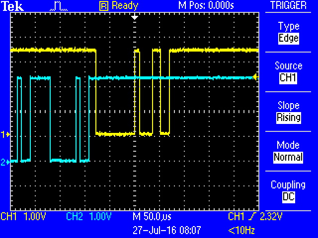
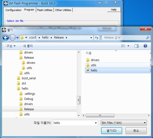
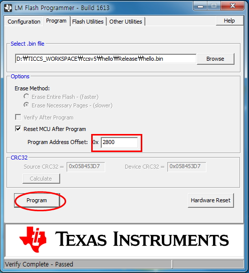
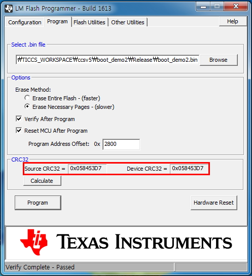
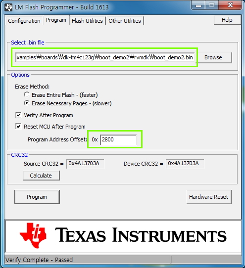
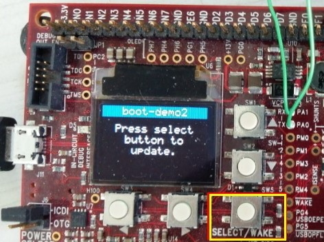
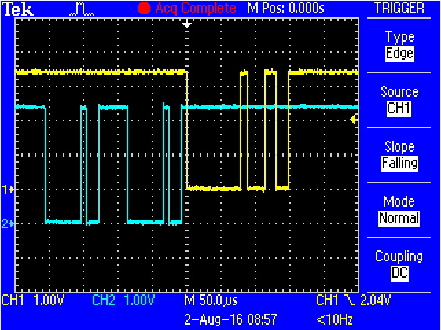
 Please check in attached picture.

What should I do ?

 thanks

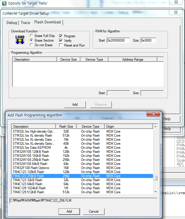
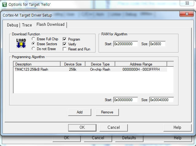
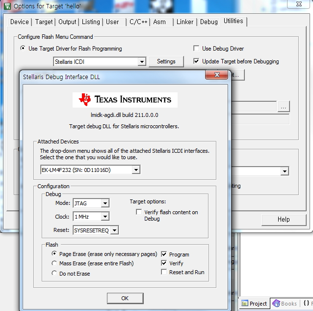
[1 STEP]  Flash Erase Only,  Erase  Select

Blank Check After Erase , Complete

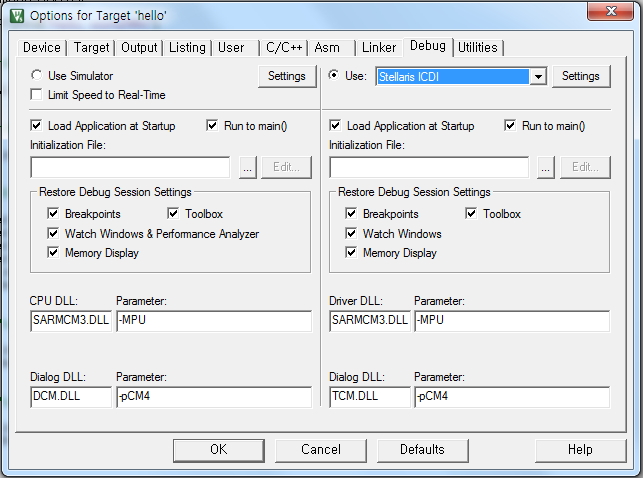
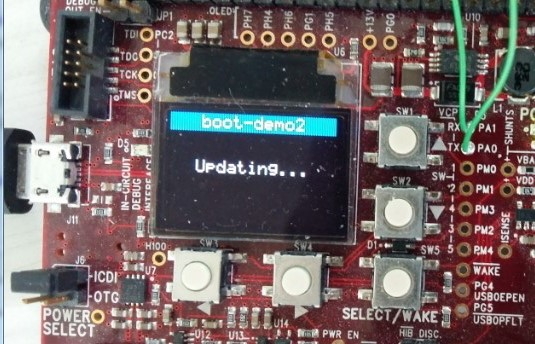
[2 STEP]  Serial_boot_bin Download,   ICDI  interface 

Download Complete 


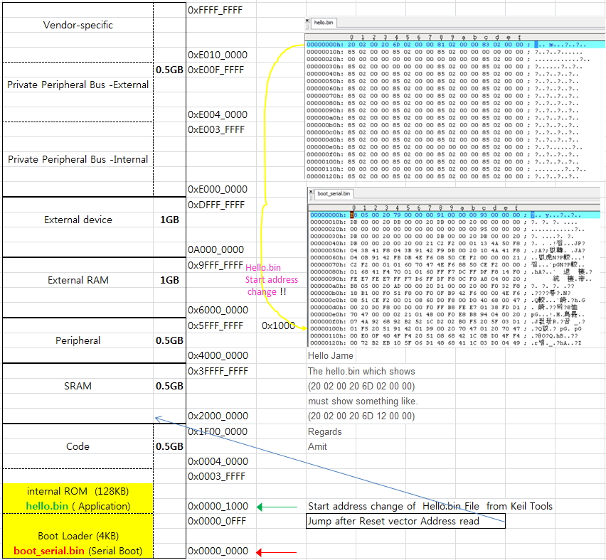
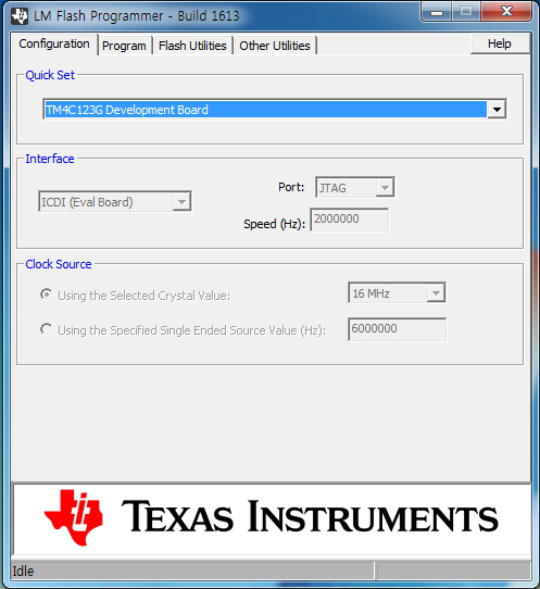
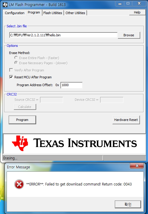
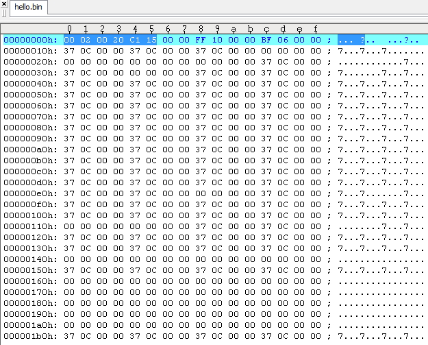
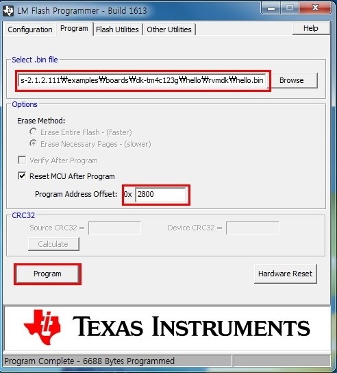
[3 STEP ]  Hello.bin Download  by  sflash Dos Mode ( 0x1000 , 1000, 4096 Address 3 type, try) Error !!


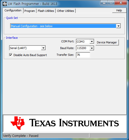
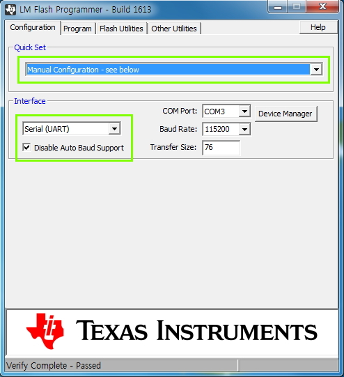
Try  to UART Interface of LM Flash Programmer, 

  • Hello Jame,

    I think in the previous post of yours, I put an update to check the communication. I haven't seen any update with the debug?

    Regards
    Amit
  • Hello Amit.

    The questions offered in the past.  but  Not found a solution.

    It's no Problem   communication  serial Port

    What should I do?

    thanks

    [    download  via interface ICD  ]

    [ Hello.bin Downloaded]

    [Hello UART Log Message  COM3  Port OK ]

  • Hello Jame

    When compiling hello.bin what is the start address being used by the cmd file in CCS project?

    Regards
    Amit
  • Hello Amit

    The image (hello.bin) was compiled 2 weeks ago

    I'm use Keil Tools , What is the start address ?

     image capture  about start address in Keil tools

    what should i do ?

    thanks.

    [ hello, compile OK]

    [ start address in Target Option]


    [ start Address in Linker option]

  • Hello James

    The Start address must not be 0x0 as you have to flash it to 0x1000. Please change the location of the reset vector and then re-try

    Regards
    Amit
  • Hello Amit

    I know Flash address 0x1000

    before Sequence step 

    1.  LM Flash Program  ->   [Confiuration] ICDI interface  -> ,  [Flash Utilities]  Erase     - (Ok)

    2.   LM Flash Program  ->   [Confiuration] ICDI interface  -> [Program] boot_serail.bin  (0x1000) - (OK)

    3.  LM Flash Program  ->    [Confiuration]  Serial(UART)  -> [Program] hello.bin (x0  or  0x1000)  - (No Good)

    3'    (Dos Mode)    sflash -c 3 -p 0x0 -d  hello.bin   or    sflash -c 3 -p 0x1000 -d  hello.bin  -(No Good)

    So, Next  try 

    4.  LM Flash Program  ->   [Confiuration] ICDI interface  -> [Program] hello.bin  (0x0) - (OK) , Log message  Good via UART

    4'  Keil Tools                  ->    [Debug] Stellaris ICDI             ->   Compile    ->  Download  hello.bin  - (OK)

    What do you think about this status?

    How to change the reset vector location you said ?

    I do not know, I saw the file(startup_rvmdk.s).

    thanks

  • Hello Jame,

    I believe the boot_serial.bin is the flash based boot loader and the hello.bin is the application that would be executed. is that correct?

    Regards
    Amit
  • Hello Amit

    yes, Correct !!
    The is boot _serial.bin (Boot Loader) in " \examples\boards\dk-tm4c123g\boot_serial "
    The is hello.bin (Application) in " \examples\boards\dk-tm4c123g\hello "

    I want to download by UART the application file over the serial boot loader

    What should i do ?

    thanks.
  • Hello James,

    The serial boot loader resides at 0x0 and the hello.bin you are trying to flash has been compiled and linked to start at 0x0. Even though you specify the program offset as 0x1000, the boot_serial.bin checks if the application is trying to overwrite it and aborts the download. You need to change the start address of the application (hello.bin) in Keil (check the documentation from Keil uVision).

    To confirm that open the hello.bin in a hex editor and paste the start of the file on the forum.

    Regards
    Amit
  • Hello Amit

    Let's check in Keil document

    Is that how changes in the CCS ?

    HEX file, do you need to check what position?

    The attached file that  header of the captured image

    thanks

    [ Hex Editor ]

  • Hello Jame

    Just as I suspected. The application binary is given the directive to be starting at 0x0. You need to change that to the correct offset as expected by the boot loader binary during link phase.

    Regards
    Amit
  • Hello Amit.

    Is that how changes in the CCS ?

    HEX file, do you need to check what position?

    I question with the above information.

    Compare 0x,& 0x1000 address values were between " boot_serial.bin"  and "Hello,bin"

    This is correct?

    0x  " boot_serial.bin"  (B8 05 00 20 79 00 00 00)

    0x  ""Hello,bin":           (20 02 00 20 6D 02 00 00)

    ------------------------------------------------------------------

    0x1000  " boot_serial.bin" (01 F5 20 51 91 42 01 D9)

    0x1000  "Hello,bin"            (85 02 00 00 85 02 00 00)

    thanks

    Add attachment [ Boot _Serial.bin]

  • Hello Jame

    The hello.bin which shows

    (20 02 00 20 6D 02 00 00)

    must show something like.

    (20 02 00 20 6D 12 00 00)

    Regards
    Amit
  • Hello Amit.

    I do not know. More details please. ?

    Set the start address in the 0x0 Keil Tools, and then hello.bin file compile the results

    This is  No Good  (20 02 00 20 6D 02 00 00).

    This is  Good        (20 02 00 20 6D 12 00 00).

    thanks

  • Hello Amit.

    I do not know. More details please. ?

    Set the start address in the 0x0 Keil Tools, and then hello.bin file compile the results

    This is  No Good  (20 02 00 20  6D 02 00 00).

    This is  Good        (20 02 00  20 6D 12 00 00).

    thanks

  • Hello Amit.

    I do not know. More details please. ?

    Set the start address in the 0x0 Keil Tools, and then hello.bin file compile the results

    This is  No Good  (20 02 00 20 6D 02 00 00).

    This is  Good        (20 02 00 20 6D 12 00 00).

    thanks

  • Hello Jame,

    I don't think you are reading the post. The start address of the hello.bin has to be modified to the position which is already put in the boot_serial.bin . i.e. 0x1000. In the last post I showed you, I tried to describe what it would look like.

    Please check Keil documents.

    Regards
    Amit
  • Hello Amit

    I do not know change the start address of hello.bin

    I'm checked  the documentation from Keil uVision (   http://www.keil.com/support/man_arm.htm   )

     - Compiler User Guide  &  µVision User's Guide

     Not found a solution.

    How to download into the flash start address is found.

    But , Stellaris ICDI not Support ,  ULINK2 Support (Attach-1.  Capture  image)

    A summarized content to the memory map. (Attach-2.  Capture image)

    what should I do ?

    thanks

    [ Attach-1 ]

    [Attach-2]

    USB to JATG Adapter ULINK2 


    Start Address (0x1000)  & Size  modifcable

    [ ICDI not Support ]

  • Hello Jame,

    Check the sct file in the project. You must modify the start address to the new address

    Regards
    Amit
  • Hello Amit 

    I'm Checked  the sct file in the project (hello).

    What does change ? 

    LR_IROM 0x00000000 0x00040000
    {
    ;
    ; Specify the Execution Address of the code and the size.
    ;
    ER_IROM 0x00000000 0x00040000
    {
    *.o (RESET, +First)
    * (InRoot$$Sections, +RO)
    }

    ;
    ; Specify the Execution Address of the data area.
    ;
    RW_IRAM 0x20000000 0x00008000
    {
    ;
    ; Uncomment the following line in order to use IntRegister().
    ;
    ;* (vtable, +First)
    * (+RW, +ZI)
    }
    }

    thanks

    [ Reference Aattachment],  Keil Target Options  [ Target]]

  • Hello Jame,

    Change the lines as...

    LR_IROM 0x00001000 0x0003F000
    {
    ;
    ; Specify the Execution Address of the code and the size.
    ;
    ER_IROM 0x00001000 0x0003F000

    Regards
    Amit
  • Hello Amit

    It has changed.   next  Compile

    This hex value was( 20 02 00 20 6D 12) at  0x Address in Hello.bin  

    but  A download error has occurred.

    what should i do ?

    Please check captured images.  [attachment]

    1.   Flash Erase  , ICDI interfce

    2.  boot_Serial, 0x ,  Download

    3.  UART Interface Change

    4. Hello , 0x1000 , Download

    thanks

    1. Hex View

    2. ICDI interface configuration

    3. Flash Erasing

    4. Erase Complete

    5. boot Serial Download Complete

    6. UART Interface Configuration

    7. hello.bin Download Error 

  • Hello Jame,

    Your binary and steps are correct. Can you please specify the following

    1. Which board are you using? And which TivaWare version?
    2. Can you send the latest boot_serial and hello bin so that I try on my side.
    3. Can you send the latest projects for the IDE?

    Regards
    Amit
  • Hello Amit

    1. Which board are you using? And which TivaWare version?

    -      Board : DK-TM4C123G   /  Version : TivaWare_C_Series-1.1

     2. Can you send the latest boot_serial and hello bin so that I try on my side.  

             I send the file. (boot_serial .bin & Hello.bin)

    3. Can you send the latest projects for the IDE?

           Yes

    4. I have a question. ? 

          0x00001000  (4KB)  ~    0x0003F000 (252KB) 

         Why is this the end of (0x3EFFF) 252KB?

    thanks

    [ attach File ( boot_serial .bin & Hello.bin)]

    boot_serial.zip

    5340.hello.zip

  • Amit 

    (notice)

    I try  new Version TivaWare_C_Series-2.1.2.111

    The result is the same problem.

    reference Attach Ver 2.1.2.111  ( boot_serial .bin & Hello.bin)

    0572.boot_serial.zip

    7824.hello.zip

  • Hello Jame,

    Thanks for the info. Can you check the projects boot_serial and boot_demo1/boot_demo2 under

    D:\ti\TivaWare_C_Series-2.1.2.111\examples\boards\dk-tm4c123g

    Regards
    Amit
  • Hello Amit

    I'm  checked boot_demo1 / boot_demo2 

    I I have a question. ?

    SCT file is not in the folder(boot_serial ) but  SCT file  is  in the folder(boot_demo1/2 )

    What is the difference? 

          LR_IROM 0x00002800 0x0003d800

         ; Specify the Execution Address of the code and the size.

         ER_IROM 0x00002800 0x0003d800

    Start Address (0x00002800)   ~ End Adress (0x0003d800)  

                                 10(KB)                                           246(KB)

    What is the status under 10KB ?

    <Download demo1 / boot_demo2>

    1. Flash  Erase  (OK)

    2 .0x  Download     ,  boot_demo1 or boot_demo2  (OK)

    3. Uart Interface ,  0x1000 Download,   Hello ( Error)

        attachment capture image

    thanks

  • Hello Jame,

    The 10KB is the start address of the application. Did you make sure that the device was in download mode and that the Disable Auto Baud check box was checked? This application has been working fine with a lot of other customers....

    Regards
    Amit
  • Hello Amit

    I had to check.   " [ v]  Disable Auto Baud Support "  

    I know. (2800) 10KB  start adress  ,  LR_IROM   [  0x00002800     ~    0x0003d800 ]  of  Boot demo1 & demo2

    My question is what is 0x ~ 0x27FF  ? 

    What should I do. ?

    thanks

  • Hello Jame,

    That is the place holder for the flash based boot loader. If the boot loader were to be expanded later on, then it would give the embedded developer free space to use, rather than causing a conflict with the application base address.

    Regards
    Amit
  • Hello Amit

    Question one meaning


    The difference between the "boot_serial"   and   "boot_demo1 & boot_demo2".

    No sct files in the folder(boot_serial


    There are sct loader files in the folder(."boot_demo1 & boot_demo2)

     Sct file of  boot_demo1. bin   or  boot_demo2. bin

    (notice).  sct File in folder 

    LR_IROM 0x00002800 (10KB Start Address)    0x0003d800  (246KB End Address)
    {
    ;
    ; Specify the Execution Address of the code and the size.
    ;
    ER_IROM 0x00002800 (10KB Start Address)    0x0003d800  (246KB End Address)


    I question why one has a different error message. ?

    Attach a picture.  boot_serial  &  boot_demo1/2  and  Hello (application)

    1.  boot_serial  +  Hello 


    2.   boot_demo1  or  demo 2  + hello


    what should i do ?

    thanks

  • Hello Jame

    Boot_demo2 uses the offset 0x2800. You need to put the program address offset as 0x2800 and make sure that the COM port is correct, baud rate is 115200 and disable auto baud support check box is checked.

    Regards
    Amit
  • Hello amit.

    1.  you said "  Boot_demo2 uses the offset 0x2800."   =>  not operation

    2. I  has validated communications port operation.  115200 ,  disable auto baud support check box  => No problem

    3. Also , validated differs from the error message Serial between  Boot.bin   and  boot_demo1/2

    Capture images attached

     ## No1  ##    Boot_demo2.bin , 0x0  +  hello.bin, 0x2800   


    ## No 2 ## 15200 ,  UART   < ---> PC communication

    Yelow( PA1_TX),  Blue(PA0_RX)

    ## No3 ##      Boot_serial.bin , 0x0  +  hello.bin, 0x1000  

    Yelow( PA1_TX),  Blue(PA0_RX)

    Board and the communication port, no problem.

    what should i do ? 

    thanks

  • Hello Jame

    boot_demo2.bin @ 0x2800 works with boot_serial.bin @ 0x0. I think you have the experiments done incorrectly.

    I would urge you to run boot_serial.bin with boot_demp2.bin as per the readme instructions in the file readme.txt of the two examples.

    Regards
    Amit
  • Hello Amit

    I'm read instructions in the file readme.txt .

    What's the problem?

    I'm try  change by  CCS Tools

    it is Compiled files (boot_serial.bin & hello.bin)  

    LM Flash Programmer download.

    The result is the same problem. " Error ........ Return code: 0043 "

     Hello. bin Hex 0x0 ( 00 02 00 20 C1 15) 

    Why the difference  Keil Tools (20 02 00 20 6D 12) ?

    what should i do ?

    thanks

  • Hello Jame,

    I just tested the boot_serial.bin flashed using JTAG to location 0x0 and boot_demo2.bin downloaded using the LMFlashProgrammer UART interface at 0x2800. Are you able to get this step working first of all?

    Regards
    Amit
  • Hello Amit.

    Are you able to get this step working first of all?

     --> Only captured image attached.

    --> Please check.

    thanks

    Boot_serial.bin (0x0)   +  Hello.bin (0x1000) 


    compile  (boot serial +boot_demo2 + hello)

    Boot_Demo2.bin (0x0)   +  Hello.bin (0x2800) 


  • Hello Jame

    In the first experiment
    compile (boot serial +boot_demo2 + hello)

    Did you try just
    compile (boot serial +boot_demo2)?

    Regards
    Amit
  • Hello Amit

    compile (boot serial +boot_demo2)?

    -> I do not know what the reason. !!!

    -> Ok  I'm just Try 

    Capture images attached

    thanks 

    1 STEP

    2 STEP

    3 STEP

    4 STEP

    5 STEP

    6 STEP

    7 STEP

    8 STEP

    9 STEP

      --------------------------------- [ add] Hello .bin  ---------------------------------

  • Hello Jame,

    The serial boot loader is expecting that the application always be at 0x2800. So compile hello project with the change in the startup offset to 0x2800 and then try the same step of loading the hello.bin with Program offset at 0x2800.

    Regards
    Amit
  • Hello Amit

     it is correct. !! 

    I have  some questions in STEP 3/ 4

    1. Step 3   0xCC00  values in which the source code?

                  [ DK-TM4C123G Board ] Yellow : PA1/TX  0xCC00  ------  UART i nterface  ------->>  [ PC(LM Flash Program) ]

                  [ DK-TM4C123G Board ]  Blue :   PA0/RX  <<----------------- UART i nterface  ---------  hello.bin , Application  [ PC(LM Flash Program) ]  

         I can not continue to download Hello bin via a UART interface.

          what shlold i do.?

    2. Step4   please answer about my question in picture

    attached [ Capture images ]

    thanks


    1. SETP


    2. STEP  ( Yellow : PA1/TX ( 0xCC00)  , Blue:  PA0/RX)


    3. STEP

    4.STEP

  • Hello Jame

    As per the diagram given, the hello.bin must be at the same place as boot_demo2.bin. Can you please attach hello.bin source code and binary to the forum?

    Regards
    Amit
  • Hello Amit.

    Source code and binary  is the same to the address below.

    C:\ti\TivaWare_C_Series-2.1.2.111\examples\boards\dk-tm4c123g\hello

    thanks. 

    i'm used  keil tools

    [reference attach]

    8270.hello.zip

  • Hello Jame

    Thank you for the project. I will try it first thing on Monday morning.

    Regards
    Amit
  • Hello Amit

    Thank you to answer. I'll wait.
  • Hello Jame,

    I updated the linker option to use 0x2800 and it now works with the DK-TM4C123 boot_serial when using the offset location 0x2800 in the LMFlashProgrammer.

    4606.hello.zip

    Regards

    Amit

  • Hello Amit

    The attached file was downloaded.

    I checked the linker option to use 0x2800  (Linker R/O Base in Keil Option)

    I'm the same as a previous question on the contents.

    How do I continue to download the only application?

    Please check captured images.

    thanks

    STEP 1

    STEP 2

    STEP 3

    STEP 4

    STEP 5

    STEP 6      Select Button,  Yellow (TX ( Board --> LM Flash Program)

    STEP 7

    STEP 8

    STEP 9

    STEP 10  Application(Hello.bin),  Yellow (TX) , Blue (RX) (Board  <<--  LM Flash Program)

    STEP 11

                     ###########################(   Download OK   ) #######################

    STEP 12

    How to continue only download applications over the boot serial  + boot_demo 2  ?

    i'm try  only download applications

  • Hello Jame,

    That is because there is no call for an boot update in your code. Please check boot_demo2 or boot_demo1 to see how UART can be re-invoked for the boot loader interface.

    Regards
    Amit
  • Hello Amit

     I'm checked  boot_demo2 or boot_demo1 to see how UART can be re-invoked for the boot loader interface.

    I do not know . explain it to me please.

    thanks.

    I have seen a source code ( boot_demo2.c)   

    [question 1]     image of a STEP 6 in  previous posting.

                             Yellow waveform,  which  send in any section of the source code ?

    [question 2]     I do not know  "   (*((void (*)(void))(*(uint32_t *)0x2c)))()   "

                              Why jump to this address?

    ( boot_demo2.c)   

    void
    JumpToBootLoader(void)
    {
    //
    // We must make sure we turn off SysTick and its interrupt before entering
    // the boot loader!
    //
    ROM_SysTickIntDisable();
    ROM_SysTickDisable();

    //
    // Disable all processor interrupts. Instead of disabling them
    // one at a time, a direct write to NVIC is done to disable all
    // peripheral interrupts.
    //
    HWREG(NVIC_DIS0) = 0xffffffff;
    HWREG(NVIC_DIS1) = 0xffffffff;

    //
    // Return control to the boot loader. This is a call to the SVC
    // handler in the boot loader.
    //
    (*((void (*)(void))(*(uint32_t *)0x2c)))();


    }

    ------------------- Main  ------------------------------------------------

    while ((ButtonsPoll(0, 0) & SELECT_BUTTON) == 0)
    {
    ROM_SysCtlDelay(ui32SysClock / 1000);
    }

    GrStringDrawCentered(&sContext, " ", -1,
    GrContextDpyWidthGet(&sContext) / 2, 20, true);
    GrStringDrawCentered(&sContext, " Updating... ", -1,
    GrContextDpyWidthGet(&sContext) / 2, 30, true);
    GrStringDrawCentered(&sContext, " ", -1,
    GrContextDpyWidthGet(&sContext) / 2, 40, true);

    //
    // Transfer control to the boot loader.
    //
    JumpToBootLoader();

    //
    // The previous function never returns but we need to stick in a return
    // code here to keep the compiler from generating a warning.
    //
    return(0);
    }

  • Hello Jame

    The JumpToBootLoader call branches to the SVC handler for the boot loader, invoking the boot loader.

    Regards
    Amit