This thread has been locked.

If you have a related question, please click the "Ask a related question" button in the top right corner. The newly created question will be automatically linked to this question.

TM4C123GH6PGE: Question QEI of DK-TM4C123G

Part Number: TM4C123GH6PGE

Hello 

Why does not the function work?

I'm use SW-Ver (TivaWare_C_Series-2.1.2.111)

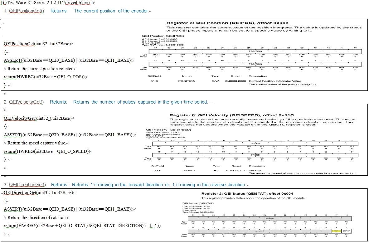
 Description in SW-TM4C-DRL-UG-2.1.2.111.pdf

1. QEIPositionGet() 

     Returns:   The current position of the encoder.

2. QEIVelocityGet()

     Returns:   Returns the number of pulses captured in the given time period.

3. QEIDirectionGet()

      Returns:  Returns 1 if moving in the forward direction or -1 if moving in the reverse direction.

thanks. 

1
2
3
4
5
6
7
8
9
10
11
12
13
14
15
16
17
18
19
20
21
22
23
24
25
26
27
28
29
30
31
32
33
34
35
36
37
38
39
40
41
42
43
44
45
46
47
48
49
50
51
52
53
54
55
56
57
58
59
60
61
62
63
64
65
66
67
68
69
70
71
72
73
74
75
76
77
78
79
80
#include <stdbool.h>
#include <stdint.h>
#include "inc/tm4c123gh6pge.h"
#include "inc/hw_memmap.h"
#include "driverlib/gpio.h"
#include "driverlib/pin_map.h"
#include "driverlib/sysctl.h"
#include "driverlib/interrupt.h"
#include "driverlib/qei.h"
#include "driverlib/uart.h"
#include "utils/uartstdio.h"
int qei_position;
int qei_velocity;
void ConsoleInit()
{
        //UART Init
        //SysCtlClockSet(SYSCTL_SYSDIV_1 | SYSCTL_USE_OSC | SYSCTL_OSC_MAIN | SYSCTL_XTAL_16MHZ);
        SysCtlPeripheralEnable(SYSCTL_PERIPH_UART0);
        SysCtlPeripheralEnable(SYSCTL_PERIPH_GPIOA);
        GPIOPinTypeUART(GPIO_PORTA_BASE, GPIO_PIN_0 | GPIO_PIN_1);
        UARTStdioConfig(0, 115200, SysCtlClockGet());
        UARTEnable(UART0_BASE);
        UARTprintf("UART Init \n");
}
void QEI1IntHandler(void)
{
    unsigned long status;
    status = QEIIntStatus(QEI1_BASE, false);  
    if ((status & QEI_INTTIMER) == QEI_INTTIMER)
    {
        QEIIntClear(QEI1_BASE, QEI_INTTIMER);
        // QEIIntClear(QEI1_BASE, QEI_INTDIR);
        qei_position = QEIPositionGet(QEI1_BASE);
        qei_velocity = QEIVelocityGet(QEI1_BASE) * QEIDirectionGet(QEI1_BASE);
        UARTprintf("position = %d \n", qei_position);
        UARTprintf("velocity = %d \n\n", qei_velocity);
    }
}
int
main(void)
{
    
    SysCtlClockSet(SYSCTL_SYSDIV_5 | SYSCTL_USE_PLL | SYSCTL_OSC_MAIN | SYSCTL_XTAL_16MHZ); // 40 MHz  200MHz/5 = ?
    ConsoleInit();
    SysCtlPeripheralEnable(SYSCTL_PERIPH_QEI1);
    SysCtlPeripheralEnable(SYSCTL_PERIPH_GPIOC);
    QEIConfigure(QEI1_BASE, QEI_CONFIG_CAPTURE_A_B | QEI_CONFIG_NO_RESET
    | QEI_CONFIG_QUADRATURE | QEI_CONFIG_SWAP, 0xFFFFFFFF);
    GPIOPinTypeQEI(GPIO_PORTC_BASE, GPIO_PIN_5 | GPIO_PIN_6);
    GPIOPinConfigure(GPIO_PC5_PHA1);
    GPIOPinConfigure(GPIO_PC6_PHB1);
    QEIVelocityConfigure(QEI1_BASE, QEI_VELDIV_2, SysCtlClockGet()/50); //20 ms period
    QEIVelocityEnable(QEI1_BASE);
    QEIEnable(QEI1_BASE);
    QEIIntEnable(QEI1_BASE, QEI_INTTIMER);
    QEIIntRegister(QEI1_BASE, &QEI1IntHandler);
    IntEnable(INT_QEI1);
    IntMasterEnable();
    GPIOPadConfigSet(GPIO_PORTC_BASE, GPIO_PIN_5 | GPIO_PIN_6, GPIO_STRENGTH_8MA_SC, GPIO_PIN_TYPE_STD_WPU);
    while(1)
    {
        UARTprintf("position = %d \n", qei_position);
        UARTprintf("velocity = %d \n\n", qei_velocity);
    }      
    
}

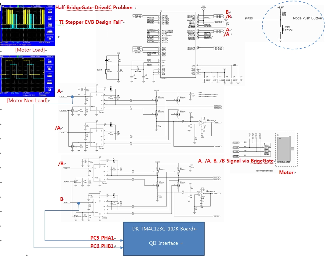
*  [ illustration ] GPIO Port C,  CH1:   PC5(PHA1), CH2: PC6(PHB1) input phase 

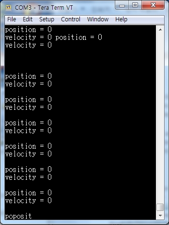
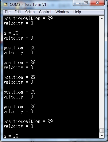
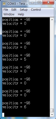
[Result Log message]

- After a few minutes

 Position = 2 

- After a few minutes

 Position = 4

- After a few minutes

8, ........ 29

  • Hello Jame

    Can you show the scope plot in a better resolution. The current scope plot does not show a quadrature phase.
  • Hello

    Same problem. ? 

    thanks

  • Hello Jame,

    Why is the maximum number of positions set to 0xFFFF.FFFF?

    QEIConfigure(QEI1_BASE, QEI_CONFIG_CAPTURE_A_B | QEI_CONFIG_NO_RESET | QEI_CONFIG_QUADRATURE | QEI_CONFIG_SWAP, 0xFFFFFFFF);
  • Hello Amit,

    i'm think  by define 32bit  full   maxposition  of  "0xFFFF.FFFF"   !!

    Question : What does Maxposition mean &  How  value should I set ?

    I just checked the hardware.

    Waveform is a problem as you have told me.

  • I just checked the software

    [ Direction CCW ]  CH1 : A1 , CH2 : B1

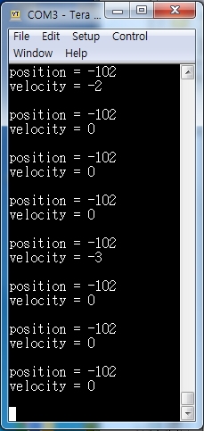
    .[ Log Message]

    [ Direction CW ]  CH1 : A1 , CH2 : B1

    .[ Log Message]

    [ Source Code Modify ]

    Addtion  

         (note) QEIVelocityConfigure(uint32_t ui32Base, uint32_t ui32PreDiv,  uint32_t ui32Period)

    1. QEIVelocityConfigure(QEI1_BASE, QEI_VELDIV_2, SysCtlClockGet());    

                      SysCtlClockGet()/50  - ->  SysCtlClockGet()

                        40Mhz/50 = 800Khz  -->    40Mhz  !!

    2. Delay. ( SysCtlDelay(SysCtlClockGet()/24);)

    Queistion :   What is mean about  given time period ?  (Velocity = 41 or 6 .....  in Log message)

                           QEIVelocityGet(),  Returns:   Returns the number of pulses captured in the given time period.


    #include <stdbool.h>
    #include <stdint.h>
    #include "inc/tm4c123gh6pge.h"
    #include "inc/hw_memmap.h"
    #include "driverlib/gpio.h"
    #include "driverlib/pin_map.h"
    #include "driverlib/sysctl.h"
    #include "driverlib/interrupt.h"
    #include "driverlib/qei.h"
    #include "driverlib/uart.h"
    #include "utils/uartstdio.h"
    
    int qei_position;
    int qei_velocity;
    
    void ConsoleInit()
    {
    		//UART Init
    
    		SysCtlPeripheralEnable(SYSCTL_PERIPH_UART0);
    		SysCtlPeripheralEnable(SYSCTL_PERIPH_GPIOA);
    
    		GPIOPinTypeUART(GPIO_PORTA_BASE, GPIO_PIN_0 | GPIO_PIN_1);
    
    		UARTStdioConfig(0, 115200, SysCtlClockGet());
    
    		UARTEnable(UART0_BASE);
    		UARTprintf("UART Init \n");
    }
    
    void QEI1IntHandler(void)
    {
    	unsigned long status;
    	status = QEIIntStatus(QEI1_BASE, false);   
    	if ((status & QEI_INTTIMER) == QEI_INTTIMER)
    	{
    		QEIIntClear(QEI1_BASE, QEI_INTTIMER);
    		qei_position = QEIPositionGet(QEI1_BASE);
    		qei_velocity = QEIVelocityGet(QEI1_BASE) * QEIDirectionGet(QEI1_BASE);
    
    	}
    }
    
    int 
    main(void)
    {
    	
    	SysCtlClockSet(SYSCTL_SYSDIV_5 | SYSCTL_USE_PLL | SYSCTL_OSC_MAIN | SYSCTL_XTAL_16MHZ); // 40 MHz  200MHz/5 = ?
    
    	ConsoleInit();
    
    	SysCtlPeripheralEnable(SYSCTL_PERIPH_QEI1);
    	SysCtlPeripheralEnable(SYSCTL_PERIPH_GPIOC);
    	QEIConfigure(QEI1_BASE, QEI_CONFIG_CAPTURE_A_B | QEI_CONFIG_NO_RESET
    	| QEI_CONFIG_QUADRATURE | QEI_CONFIG_SWAP, 0xFFFFFFFF);
    	GPIOPinTypeQEI(GPIO_PORTC_BASE, GPIO_PIN_5 | GPIO_PIN_6);
    
    
    	GPIOPinConfigure(GPIO_PC5_PHA1);
    	GPIOPinConfigure(GPIO_PC6_PHB1);
    	QEIVelocityConfigure(QEI1_BASE, QEI_VELDIV_2, SysCtlClockGet());
    	QEIVelocityEnable(QEI1_BASE);
    	QEIEnable(QEI1_BASE);
    
    	QEIIntEnable(QEI1_BASE, QEI_INTTIMER);
    	QEIIntRegister(QEI1_BASE, &QEI1IntHandler);
    	IntEnable(INT_QEI1);
    	IntMasterEnable();
    
    	GPIOPadConfigSet(GPIO_PORTC_BASE, GPIO_PIN_5 | GPIO_PIN_6, GPIO_STRENGTH_8MA_SC, GPIO_PIN_TYPE_STD_WPU);
    	while(1)
    	{
    		SysCtlDelay(SysCtlClockGet()/24);
    		UARTprintf("position = %d \n", qei_position);
    		UARTprintf("velocity = %d \n\n", qei_velocity);
    	}		


    }
    

    .[ Log Message]

  • Hello Jame

    The MAX position should be set as the number of steps that would be encountered during one full movement of the motor from the encoder.
  • Hello Amit.

    What is the number of step ?

    Please explain in detail.

    (Reference)
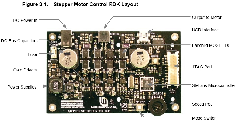
    it is Basic step angle 1.8 degree of stepping motor in rdk-stepper(Stellaris)

    thanks.
  • Hello Jame

    How many step will it take to complete a full rotation of the motor as seen by the rotary encoder. That would be the MAX positions.

  • Hello Amit

    Is there a problem  MaxPosition value?

    Use as Stepper RDK instead of rotary encoder.

    Starts, stops, and changes the motor rotation every time the mode switching button is pressed.

    The number of pulses per revolution(ppr) is unknown. !!

    How do you know what the Maxposition value should be?

    Can I apply a quadrature encoder interrupt source to QEI_INTDIR?

    thanks

    [illustration-1]

    [illustration-2]

  • Hello Jame

    Then what is generating the Quadrature pulses?
  • Hello Amit

    Generation Quardrature Plus  is a  Stellaris Micocontroller in Stepper RDK

    thanks.

    Ch1:  A ,  Ch2 : B ,  Ch3: /A ,  Ch4: /B


  • Hello Amit

    Is there a problem?

    Why did you check

    thanks.
  • Hello Jame

    The PWM pulses being generated are not the QEI inputs. The PWM pulses are used for the control of the 3 phase drives.
  • I do not know if it is not an input condition.. !!

    Why ?

    I attached the learned QEI timing diagram.

    thanks

    [illustration 1 ]

    [illustration 2 ]

  • Hello Jame

    If you check the waveform, they are not truly quadrature in nature. True Quadrature comes from the encoder mounted on the motor.
  • Hello  Amit

    I have another question.

    How do I set the source code?

     RPM = (clock x (2^VELDIV) x Speed x 60 ) / (Timer Load  x  ppr x edge)


    thanks. 

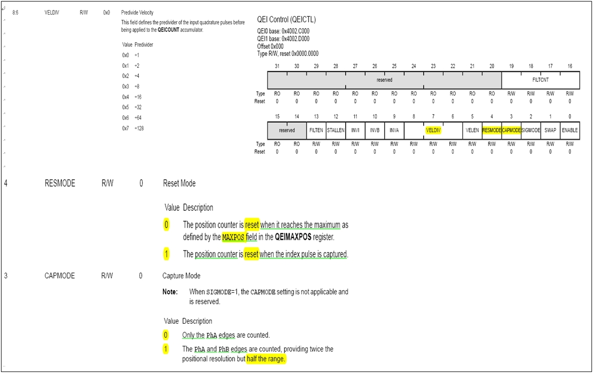
      [illustration 1]    Description In Datasheet


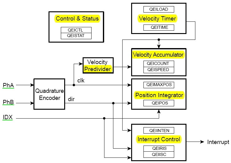
    [illustration 2]    QEI Block Diagram 

    I have analyzed the above source code.

    ISR :

    qei_position = QEIPositionGet(QEI1_BASE);

     qei_velocity = QEIVelocityGet(QEI1_BASE) * QEIDirectionGet(QEI1_BASE);

    Main :

    QEIConfigure(QEI1_BASE, QEI_CONFIG_CAPTURE_A_B | QEI_CONFIG_NO_RESET| QEI_CONFIG_QUADRATURE | QEI_CONFIG_SWAP, 0xFFFFFFFF);

    QEIVelocityConfigure(QEI1_BASE, QEI_VELDIV_2, SysCtlClockGet()/50);

    QEIIntEnable(QEI1_BASE, QEI_INTTIMER);


       (reference)

    1. void QEIConfigure (uint32_t ui32Base, uint32_t ui32Config, uint32_t ui32MaxPosition)    ,ui32MaxPosition specifies the maximum position value.

    2. void QEIVelocityConfigure (uint32_t ui32Base, uint32_t ui32PreDiv, uint32_t ui32Period)  ,ui32Period specifies the number of clock ticks over which to measure the velocity;

    3. void QEIIntEnable (uint32_t ui32Base, uint32_t ui32IntFlags)  ,ui32IntFlags is a bit mask of the interrupt sources ( QEI_INTERROR, QEI_INTDIR, QEI_INTTIMER, or QEI_INTINDEX)


      [illustration 3]    Reference  Lib &  SW

  • Hello Thao,

    What are the parameters that you have for the equation?
  • Hello  Amit

    parameters descriptions are explained below  [illustration 1].

    (Reference)

           datasheet attached. ( Chapter QEI ) 

    thanks

    tm4c123gh6pge_19 Nov 2013(Rev.C).pdf

  • Hello Jame

    I understand the data sheet specification. But what is the specification for your design?