This thread has been locked.

If you have a related question, please click the "Ask a related question" button in the top right corner. The newly created question will be automatically linked to this question.

CCS/SW-EK-TM4C1294XL: Display value in 20x4 LCD with TM4C 1294XL

Part Number: SW-EK-TM4C1294XL

Tool/software: Code Composer Studio

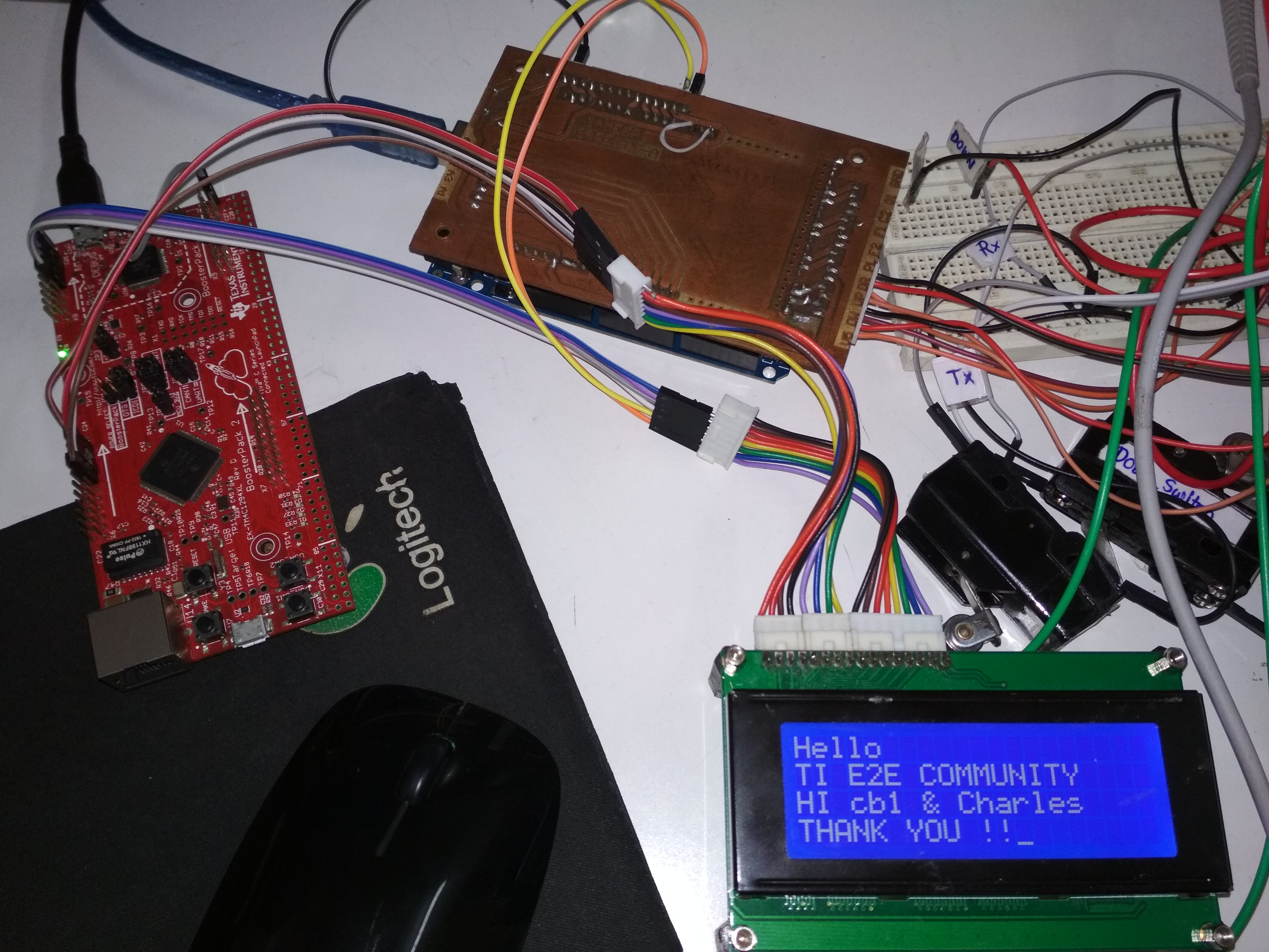
I WANT TO INTERFACE QC2004A LCD WITH TM4C 1294XL.

BELOW IS MY CODE. NO ERROR. BUT DISPLAY IS BLANK. 

CONNECTION:  RS-PB4,  EN-PB5,  D4-PE0,  D5-PE1,  D6-PE2,  D7-PE3,  VSS-GND,  VDD-5V,  VEE[PIN 3]-3.3V,  R/W-GND,  Backlight Anode-3.3V.

PLEASE SUGGEST POSSIBLE SOLUTION / POINT OUT ERRORS.

#include <stdint.h>
#include <stdbool.h>
#include <string.h>
#include "inc/hw_memmap.h"
#include "inc/hw_types.h"
#include "driverlib/debug.h"
#include "driverlib/sysctl.h"
#include "driverlib/gpio.h"

/*
#define Function_set         0x28  //4bit_2line_5x7
#define Scroll_right         0x1E
#define Scroll_left          0x18
#define Return_Home          0x02
#define Increment_cursor     0x06
#define Decrement_cursor     0x04
#define DisplayON_CursorON   0x0E  //Display ON-OFF control
#define Blinking_cursor      0x0F
#define Invisible_cursor     0x0C
#define Blank_display        0x08
#define Clear_display        0x01
#define SetCursorto1         0x80
#define SetCursorto2         0xC0
#define SetCursorto3         0x94
#define SetCursorto4         0xD4
 */
void Initialize_LCD(void);
void string_to_lcd(unsigned char *s);
void LCD_write(unsigned char,unsigned int);


void main()
{
    SysCtlClockFreqSet((SYSCTL_XTAL_25MHZ | SYSCTL_OSC_MAIN | SYSCTL_USE_PLL | SYSCTL_CFG_VCO_480), 120000000);
    SysCtlDelay(100000);//2ms
    SysCtlPeripheralEnable(SYSCTL_PERIPH_GPIOE);
    SysCtlDelay(100000);
    SysCtlPeripheralEnable(SYSCTL_PERIPH_GPIOB);
    SysCtlDelay(100000);
    GPIOPinTypeGPIOOutput(GPIO_PORTE_BASE, GPIO_PIN_0|GPIO_PIN_1|GPIO_PIN_2|GPIO_PIN_3);
    SysCtlDelay(100000);
    GPIOPinTypeGPIOOutput(GPIO_PORTB_BASE, GPIO_PIN_4|GPIO_PIN_5);
    SysCtlDelay(100000);

    GPIOPinWrite(GPIO_PORTE_BASE, GPIO_PIN_0|GPIO_PIN_1|GPIO_PIN_2|GPIO_PIN_3, 0x00);
    SysCtlDelay(2000000);//20ms
    Initialize_LCD();
    while(1){
    LCD_write(0X80,0);
    string_to_lcd("1234");
    LCD_write(0XC0,0);
    string_to_lcd("QWER");
    LCD_write(0X94,0);
    string_to_lcd("ASDF");
    LCD_write(0XD4,0);
    string_to_lcd("ZXCV");
    SysCtlDelay(0XFFFFFF00);
    }
}

void Initialize_LCD(void)
{
    GPIOPinWrite(GPIO_PORTB_BASE, GPIO_PIN_4, 0); //RS PIN LOW
    SysCtlDelay(5000);
    GPIOPinWrite(GPIO_PORTB_BASE, GPIO_PIN_5, 0); //EN PIN LOW
    SysCtlDelay(5000);

    LCD_write(0x20,0);
    SysCtlDelay(5000);
    LCD_write(0x08,0);
    SysCtlDelay(5000);
    LCD_write(0x01,0);
    SysCtlDelay(5000);
    LCD_write(0x06,0);
    SysCtlDelay(5000);
    LCD_write(0x0E,0);
    SysCtlDelay(5000);
    LCD_write(0X01,0);
    SysCtlDelay(100000);
}

void LCD_write(unsigned char data,unsigned int RS)
{
    GPIOPinWrite(GPIO_PORTB_BASE, GPIO_PIN_4, RS); //Cammand/Data

    SysCtlDelay(5000);
    GPIOPinWrite(GPIO_PORTB_BASE, GPIO_PIN_5, 1);
    SysCtlDelay(5000);
    //GPIOPinWrite(GPIO_PORTE_BASE, GPIO_PIN_0, ((data & 0X10)>>4));
    //GPIOPinWrite(GPIO_PORTE_BASE, GPIO_PIN_1, ((data & 0X20)>>5));
    //GPIOPinWrite(GPIO_PORTE_BASE, GPIO_PIN_2, ((data & 0X40)>>6));
    //GPIOPinWrite(GPIO_PORTE_BASE, GPIO_PIN_3, ((data & 0X80)>>7));
    GPIOPinWrite(GPIO_PORTE_BASE, GPIO_PIN_3|GPIO_PIN_2|GPIO_PIN_1|GPIO_PIN_0, ((data & 0XF0)>>4));
    SysCtlDelay(5000);
    GPIOPinWrite(GPIO_PORTB_BASE, GPIO_PIN_5, 0);
    SysCtlDelay(5000);

    SysCtlDelay(5000);
    GPIOPinWrite(GPIO_PORTB_BASE, GPIO_PIN_5, 1);
    SysCtlDelay(5000);
    //GPIOPinWrite(GPIO_PORTE_BASE, GPIO_PIN_0, ( data & 0X01));
    //GPIOPinWrite(GPIO_PORTE_BASE, GPIO_PIN_1, ((data & 0X02)>>1));
    //GPIOPinWrite(GPIO_PORTE_BASE, GPIO_PIN_2, ((data & 0X04)>>2));
    //GPIOPinWrite(GPIO_PORTE_BASE, GPIO_PIN_3, ((data & 0X08)>>3));
    GPIOPinWrite(GPIO_PORTE_BASE, GPIO_PIN_3|GPIO_PIN_2|GPIO_PIN_1|GPIO_PIN_0, (data & 0X0F));
    SysCtlDelay(5000);
    GPIOPinWrite(GPIO_PORTB_BASE, GPIO_PIN_5, 0);
    SysCtlDelay(5000);
}

void string_to_lcd(unsigned char *s)
{
    unsigned int slen;
    slen=strlen(s);
    while(slen>0)
    {
        unsigned char D=*s;
        LCD_write(*s,1);
        SysCtlDelay(0XFFFF0000);
        slen--;
        s++;
    }
}

  • Krishnat Pawar said:
    PLEASE SUGGEST POSSIBLE SOLUTION / POINT OUT ERRORS.

    That's quite a task listing - is it not?

    You do (neither) yourself - nor your helpers - any favor by electing, "4 Bit LCD Mode."     The "saving" of 4 GPIO is achieved at much greater SW complexity - and loss of display "robustness!"    (as ANY glitch upon "E" will throw the Lcd into complete disorder! ... i.e. the dual, "nibble" transfer sequence will be "unpaired.")

    Your understanding of this vendor's most helpful API demands further review (especially GPIO Reads/Writes).     Here's (just one) example:

    Krishnat Pawar said:
    GPIOPinWrite(GPIO_PORTB_BASE, GPIO_PIN_5, 1);

    While the use of "1" to "Set a Bit" is usual - it FAILS here!    Your review of the SW-DRL-User Guide reveals that the "3rd parameter must be the "bit-packed/valued" of the targeted bit."   (which is NOT "1" - instead GPIO_PIN_5 has the bit-packed value of 32.   Likewise "PIN_7 is 128, PIN_4 is 16, PIN_0 IS 1.)

    There are bound to be even further code errors - yet your "retreat from the needless complexity demanded by "Four Bit LCD Mode" is paramount!

    Your search of this forum will reveal my (multiple) past postings - some of which included the "Grandfather LCD Control IC's spec" - which revealed the complex Initialization Code and Timing.   Getting that (at all wrong) DOOMS all subsequent effort.

    You note the Lcd's contrast pin as set to 3V3 - while possible - it is far more usual that the contrast pin is adjusted near GND - check your display's data sheet for the specifics.

    Four Bit LCD Mode is (most properly) reserved for high volume Apps - and cannot justify the extra "time/attention" demanded - so that 4 GPIO are saved...  (for a limited volume usage...)

  • Hi Krishnat ,

     I think the best is for you to check on the logic analyzer if all the signals are properly generated to the LCD with respect to the timing requirements demanded by your LCD display. Check if the LCD has proper power supply and if you are manipulating the signals correctly. Below is a reference for how someone has done it in Raspberry Pi.

    https://www.raspberrypi-spy.co.uk/2012/08/20x4-lcd-module-control-using-python/

    LCD Pin Function Pi Function Pi Pin
    01 GND GND P1-06
    02 +5V +5V P1-02
    03 Contrast
    04 RS GPIO7 P1-26
    05 RW GND P1-06
    06 E GPIO8 P1-24
    07 Data 0
    08 Data 1
    09 Data 2
    10 Data 3
    11 Data 4 GPIO25 P1-22
    12 Data 5 GPIO24 P1-18
    13 Data 6 GPIO23 P1-16
    14 Data 7 GPIO18 P1-12
    15 +5V via 560 ohm
    16 GND P1-06

    #!/usr/bin/python
    #--------------------------------------
    #    ___  ___  _ ____
    #   / _ \/ _ \(_) __/__  __ __
    #  / , _/ ___/ /\ \/ _ \/ // /
    # /_/|_/_/  /_/___/ .__/\_, /
    #                /_/   /___/
    #
    #  lcd_16x2.py
    #  20x4 LCD Test Script with
    #  backlight control and text justification
    #
    # Author : Matt Hawkins
    # Date   : 06/04/2015
    #
    # www.raspberrypi-spy.co.uk/
    #
    #--------------------------------------
     
    # The wiring for the LCD is as follows:
    # 1 : GND
    # 2 : 5V
    # 3 : Contrast (0-5V)*
    # 4 : RS (Register Select)
    # 5 : R/W (Read Write)       - GROUND THIS PIN
    # 6 : Enable or Strobe
    # 7 : Data Bit 0             - NOT USED
    # 8 : Data Bit 1             - NOT USED
    # 9 : Data Bit 2             - NOT USED
    # 10: Data Bit 3             - NOT USED
    # 11: Data Bit 4
    # 12: Data Bit 5
    # 13: Data Bit 6
    # 14: Data Bit 7
    # 15: LCD Backlight +5V**
    # 16: LCD Backlight GND
     
    #import
    import RPi.GPIO as GPIO
    import time
     
    # Define GPIO to LCD mapping
    LCD_RS = 7
    LCD_E  = 8
    LCD_D4 = 25
    LCD_D5 = 24
    LCD_D6 = 23
    LCD_D7 = 18
    LED_ON = 15
     
    # Define some device constants
    LCD_WIDTH = 20    # Maximum characters per line
    LCD_CHR = True
    LCD_CMD = False
     
    LCD_LINE_1 = 0x80 # LCD RAM address for the 1st line
    LCD_LINE_2 = 0xC0 # LCD RAM address for the 2nd line
    LCD_LINE_3 = 0x94 # LCD RAM address for the 3rd line
    LCD_LINE_4 = 0xD4 # LCD RAM address for the 4th line
     
    # Timing constants
    E_PULSE = 0.0005
    E_DELAY = 0.0005
     
    def main():
      # Main program block
     
      GPIO.setmode(GPIO.BCM)       # Use BCM GPIO numbers
      GPIO.setup(LCD_E, GPIO.OUT)  # E
      GPIO.setup(LCD_RS, GPIO.OUT) # RS
      GPIO.setup(LCD_D4, GPIO.OUT) # DB4
      GPIO.setup(LCD_D5, GPIO.OUT) # DB5
      GPIO.setup(LCD_D6, GPIO.OUT) # DB6
      GPIO.setup(LCD_D7, GPIO.OUT) # DB7
      GPIO.setup(LED_ON, GPIO.OUT) # Backlight enable
     
      # Initialise display
      lcd_init()
     
      # Toggle backlight on-off-on
      lcd_backlight(True)
      time.sleep(0.5)
      lcd_backlight(False)
      time.sleep(0.5)
      lcd_backlight(True)
      time.sleep(0.5)
     
      while True:
     
        # Send some centred test
        lcd_string("--------------------",LCD_LINE_1,2)
        lcd_string("Rasbperry Pi",LCD_LINE_2,2)
        lcd_string("Model B",LCD_LINE_3,2)
        lcd_string("--------------------",LCD_LINE_4,2)
     
        time.sleep(3) # 3 second delay
     
        lcd_string("Raspberrypi-spy",LCD_LINE_1,3)
        lcd_string(".co.uk",LCD_LINE_2,3)
        lcd_string("",LCD_LINE_3,2)
        lcd_string("20x4 LCD Module Test",LCD_LINE_4,2)
     
        time.sleep(3) # 20 second delay
     
        # Blank display
        lcd_byte(0x01, LCD_CMD)
     
        time.sleep(3) # 3 second delay
     
    def lcd_init():
      # Initialise display
      lcd_byte(0x33,LCD_CMD) # 110011 Initialise
      lcd_byte(0x32,LCD_CMD) # 110010 Initialise
      lcd_byte(0x06,LCD_CMD) # 000110 Cursor move direction
      lcd_byte(0x0C,LCD_CMD) # 001100 Display On,Cursor Off, Blink Off
      lcd_byte(0x28,LCD_CMD) # 101000 Data length, number of lines, font size
      lcd_byte(0x01,LCD_CMD) # 000001 Clear display
      time.sleep(E_DELAY)
     
    def lcd_byte(bits, mode):
      # Send byte to data pins
      # bits = data
      # mode = True  for character
      #        False for command
     
      GPIO.output(LCD_RS, mode) # RS
     
      # High bits
      GPIO.output(LCD_D4, False)
      GPIO.output(LCD_D5, False)
      GPIO.output(LCD_D6, False)
      GPIO.output(LCD_D7, False)
      if bits&0x10==0x10:
        GPIO.output(LCD_D4, True)
      if bits&0x20==0x20:
        GPIO.output(LCD_D5, True)
      if bits&0x40==0x40:
        GPIO.output(LCD_D6, True)
      if bits&0x80==0x80:
        GPIO.output(LCD_D7, True)
     
      # Toggle 'Enable' pin
      lcd_toggle_enable()
     
      # Low bits
      GPIO.output(LCD_D4, False)
      GPIO.output(LCD_D5, False)
      GPIO.output(LCD_D6, False)
      GPIO.output(LCD_D7, False)
      if bits&0x01==0x01:
        GPIO.output(LCD_D4, True)
      if bits&0x02==0x02:
        GPIO.output(LCD_D5, True)
      if bits&0x04==0x04:
        GPIO.output(LCD_D6, True)
      if bits&0x08==0x08:
        GPIO.output(LCD_D7, True)
     
      # Toggle 'Enable' pin
      lcd_toggle_enable()
     
    def lcd_toggle_enable():
      # Toggle enable
      time.sleep(E_DELAY)
      GPIO.output(LCD_E, True)
      time.sleep(E_PULSE)
      GPIO.output(LCD_E, False)
      time.sleep(E_DELAY)
     
    def lcd_string(message,line,style):
      # Send string to display
      # style=1 Left justified
      # style=2 Centred
      # style=3 Right justified
     
      if style==1:
        message = message.ljust(LCD_WIDTH," ")
      elif style==2:
        message = message.center(LCD_WIDTH," ")
      elif style==3:
        message = message.rjust(LCD_WIDTH," ")
     
      lcd_byte(line, LCD_CMD)
     
      for i in range(LCD_WIDTH):
        lcd_byte(ord(message[i]),LCD_CHR)
     
    def lcd_backlight(flag):
      # Toggle backlight on-off-on
      GPIO.output(LED_ON, flag)
     
    if __name__ == '__main__':
     
      try:
        main()
      except KeyboardInterrupt:
        pass
      finally:
        lcd_byte(0x01, LCD_CMD)
        lcd_string("Goodbye!",LCD_LINE_1,2)
        GPIO.cleanup()

  • Hi Charles,

    Looking at this (Rasp) fellow's "LCD Init" - I do not believe it to be correct.    Improper initialization - as stated - DOOMS all subsequent efforts.
    In addition - the "critical" contrast pin's level (Pin 3) - has been "unspecified!"     Attention to such detail IS required...   (throws all that follows under suspicion...)

    The "lack of robustness" via 4-Bit Mode is little recognized - yet VERY REAL - and is employed in your presented example.   As you know - a clear Violation of KISS!    "Saving 4 GPIO - at risk of a highly disordered display screen" - proves an unsatisfactory, "Risk vs. Reward."

  • Hi cb1,
    Thanks for catching the offending code line (appearing in multiple places using GPIOPinWrite) and the recommendation.
  • Hi Charles,

    It is my belief that such "offending code lines" occur w/in, "O.P.'s code" AS WELL as "Rasp's code!"        (and do note that Rasp "ducked" the  (necessary voltage level setting of display's (critical) Contrast pin!)

    Not all code - found "free" on the net - is insured to "function as desired..."

    You (must) have noted that (both) o.p. and "Rasp" have chosen the far more demanding, more complex, "Four Bit LCD Mode!"     By your presentation of the "Rasp" code (which I believe incorrect) is it your opinion that "Code Ease & Robustness" should be TRADED for the "saving of 4 GPIO?"    

    Such is NEVER my recommendation...    KISS - even though banned here - especially as banned here - truly RULES!

  • HI,

    THANK YOU FOR SUPPORT.

    CONNECTION:  VSS[PIN-1]-GND,  VDD[PIN-1]-5V,  VEE[PIN 3]-VARIABLE POT, RS[PIN 4]-PB4,  R/W[PIN 5]-GND,  EN[PIN 6]-PB5, DB0-DB3- N.C. D4-PE0,  D5-PE1,  D6-PE2,  D7-PE3,  A[PIN 15]-VARIABLE POT, A[PIN 16]-GND

    #include <stdint.h>
    #include <stdbool.h>
    #include <string.h>
    #include "inc/hw_memmap.h"
    #include "inc/hw_types.h"
    #include "driverlib/debug.h"
    #include "driverlib/sysctl.h"
    #include "driverlib/gpio.h"
    
    
    void Initialize_LCD(void);
    void string_to_lcd(unsigned char *s);
    void LCD_write(unsigned char,unsigned int);
    
    
    void main()
    {
    SysCtlClockFreqSet((SYSCTL_XTAL_25MHZ | SYSCTL_OSC_MAIN | SYSCTL_USE_PLL | SYSCTL_CFG_VCO_480), 120000000);
    SysCtlDelay(100000);//2ms
    SysCtlPeripheralEnable(SYSCTL_PERIPH_GPIOE);
    SysCtlDelay(100000);
    SysCtlPeripheralEnable(SYSCTL_PERIPH_GPIOB);
    SysCtlDelay(100000);
    GPIOPinTypeGPIOOutput(GPIO_PORTE_BASE, GPIO_PIN_0|GPIO_PIN_1|GPIO_PIN_2|GPIO_PIN_3);
    SysCtlDelay(100000);
    GPIOPinTypeGPIOOutput(GPIO_PORTB_BASE, GPIO_PIN_4|GPIO_PIN_5);
    SysCtlDelay(100000);
    
    GPIOPinWrite(GPIO_PORTE_BASE, GPIO_PIN_0|GPIO_PIN_1|GPIO_PIN_2|GPIO_PIN_3, 0x00);
    SysCtlDelay(2000000);//20ms
    Initialize_LCD();


    LCD_write(0X80,0);
    string_to_lcd("Hello");
    LCD_write(0XC0,0);
    string_to_lcd("TI E2E COMMUNITY");
    LCD_write(0X94,0);
    string_to_lcd("HI cb1 & Charles");
    LCD_write(0XD4,0);
    string_to_lcd("THANK YOU !!");
    SysCtlDelay(0XFFFFFF00);
    
    while(1){
    }
    }
    
    void Initialize_LCD(void)
    {
    GPIOPinWrite(GPIO_PORTB_BASE, GPIO_PIN_4, 0xEF); //RS PIN LOW
    SysCtlDelay(5000);
    GPIOPinWrite(GPIO_PORTB_BASE, GPIO_PIN_5, 0xDF); //EN PIN LOW
    SysCtlDelay(5000);
    
    LCD_write(0x33,0);
    SysCtlDelay(5000);
    LCD_write(0x32,0);
    SysCtlDelay(5000);
    LCD_write(0x06,0);
    SysCtlDelay(5000);
    LCD_write(0x0E,0);
    SysCtlDelay(5000);
    LCD_write(0x28,0);
    SysCtlDelay(5000);
    LCD_write(0X01,0);
    SysCtlDelay(10000000);
    }
    
    void LCD_write(unsigned char data,unsigned int RS)
    {
    if(RS==0)
    GPIOPinWrite(GPIO_PORTB_BASE, GPIO_PIN_4, 0xEF); //Cammand
    else
    GPIOPinWrite(GPIO_PORTB_BASE, GPIO_PIN_4, 0xFF); //Data
    
    SysCtlDelay(5000);
    GPIOPinWrite(GPIO_PORTB_BASE, GPIO_PIN_5, 0xFF);
    SysCtlDelay(5000);
    
    GPIOPinWrite(GPIO_PORTE_BASE, GPIO_PIN_3|GPIO_PIN_2|GPIO_PIN_1|GPIO_PIN_0, ((data & 0XF0)>>4));
    SysCtlDelay(5000);
    GPIOPinWrite(GPIO_PORTB_BASE, GPIO_PIN_5, 0xDF);
    SysCtlDelay(5000);
    
    SysCtlDelay(5000);
    GPIOPinWrite(GPIO_PORTB_BASE, GPIO_PIN_5, 0xFF);
    SysCtlDelay(5000);
    
    GPIOPinWrite(GPIO_PORTE_BASE, GPIO_PIN_3|GPIO_PIN_2|GPIO_PIN_1|GPIO_PIN_0, (data & 0X0F));
    SysCtlDelay(5000);
    GPIOPinWrite(GPIO_PORTB_BASE, GPIO_PIN_5, 0xDF);
    SysCtlDelay(5000);
    }
    
    void string_to_lcd(unsigned char *s)
    {
    unsigned int slen;
    slen=strlen(s);
    while(slen>0)
    {
    unsigned char D=*s;
    LCD_write(*s,1);
    SysCtlDelay(1000000);
    slen--;
    s++;
    }
    
    }

  • **** LIKE!!!!! *****

    That is one highly creative Thank You message!!!!

  • Glad your problem is solved.
  • So INSPIRED a POST demands a "Double LIKE!"   (for execution - especially your photo!)    (I actually thought, "How great it would be if poster "showed his screen" (as I read your display message) and then saw that you, "Did just that!"

    *** LIKE ***    

    *** LIKE ***

    That said - having been (very) successful in the display biz - ALL EIGHT DATA Bits (wiring) reveal w/in your great photo!     (law-school "evidence training")

    (I remain uncertain (even doubtful) over the correctness of your 4 bit initialization - although you did modify it between first & second postings.)

    The fact that "ANY glitch upon "E" will "Throw your display into disorder" - as "DIRECT CONSEQUENCE OF 4 BIT MODE" - introduces an element of risk!    (not properly "rewarded" via the saving of 4 GPIO!)    

    In addition the "write (or read) time" for each/every character is DOUBLED!

    So rare that "helpers" are rewarded - great kindness on your part - and IMAGINATIVELY DELIVERED!     (Switching to (proper) 8 bit mode adds ROBUSTNESS to your effort...)