This thread has been locked.

If you have a related question, please click the "Ask a related question" button in the top right corner. The newly created question will be automatically linked to this question.

TM4C1294NCPDT: EK-TM4C1294XL I2C + FT5306 communication problem

Part Number: TM4C1294NCPDT

Hey, 

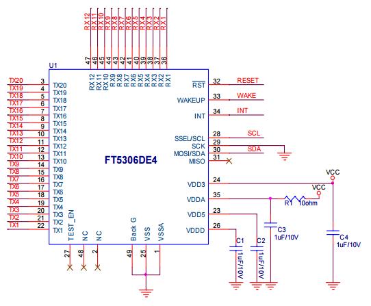
I am currently working to interface the Focal Touch Capacitive Touch Screen which has the FT5306 chip onboard and comes prepackaged. I am unable, however, to communicate with the device with my TIVA TM4C129 MCU with it. When I try to send and read data to the touch panel, I seem to be getting a NACK and am unsure as to why it that is. When I press down on the touch panel, I'm also not able to see the INT signal change meaning that I'm not sure if the touch panel is being detected correctly. 

I've probed the SDA and SCL lines and observe the following manner when I begin my transmission and attempt to write to register 0x38. I've looked through the TI document at  and am still unable to understand why I am not receiving any communication with the touch controller.

Any help would be sincerely appreciated!

Thanks

  • Sorry for not including the I2C signal lines in the original post - The blue is the SDA line and the green is the SCL line.

  • Feel your pain - IIRC - I resolved a (highly) similar issue - with (your) or a touch-screen (extremely) similar.

    Your signal levels look good - yet there is (some) rounding - have you employed, "External Pull-Up Resistors" (~10K) - rather than using the MCU's (too high value) internal ones?

    Here - once more - some quick I2C Diagnostic Guides:

    • Do your scope caps result from "Attachment at the Touch-Chip's specified I2C pins?"    Even if - and especially if - those "probe points" prove "inconvenient?"   (so often - we find client's (incorrectly manage) the interconnect - although they SWEAR that they've (really) checked!  
    • Proves always wise to, "Give the interface the best chance to WORK!"    Thus operating at the lowest, standard speed (100k) is highly suggested.  
    • What is the length of your interconnect?   I2C is "short range" (30mm max is my preference, 20mm - even better) - excessive length adds capacitance & invites signal reflection/rounding. 
    • Is your power supply adequate for the "Added Demands" imposed by the:  Display, Touch-Screen & (other) devices - resident upon your (assumed) Display Board?
    • On most such Touch Controllers - the "Interrupt upon Touch" (usually) is not dependent upon Touch Chip set-up.    As you report,  "No interrupt emitted" - is it possible that your "mounting of the touch screen" - has produced a "continuing force" (your touch panel is being "squeezed" - usually at the perimeter - by the larger, containing panel) which "Prevents the generation" of subsequent, Touch-generated interrupts.
    • It's my sense that your scope cap would improve - if the I2C channels would be "vertically offset" and identified - which yields improved viewing.

    Firm/I are BIG proponents of "KISS" - your Touch Chip IS complex - I'd much prefer you to "start" w/a far simpler,  I2C based - small capacity - EEProm.    Armed w/that experience, confidence & mastery - your attack of the (much) higher mountain - most always proves enhanced...

  • Hello,

    Thank you for your quick response! Unfortunately, I am still unable to send data to the device and am continuing to get a NACK.

    - I have employed external pull-up resistors rather than using the MCU's internal ones.

    - I've triple checked my connections and confirm that they are correct.

    - I've lowered the speed to 100kHz but that didn't help.

    - I am currently using jumper wires to connect with the device.

    - I am using an external power supply to power up the touch controller so can confirm that there is enough power for the device.

    If I had to guess anything, I think the touch controller isn't being woken up correctly and so the chip remains in Hibernate mode but I'm driving the WAKE pin high on the controller and unsure what else to do to change the power to active mode.

    Thanks

    Attached is the updated timing diagram of I2C serial communication:

  • Thank you - appreciated. I've not had the time to comb thru your Touch Manual - and confirm that 0x38 is indeed - the correct Slave Address.

    Your scope cap - now "normal/customary" vertically spaced overlap - is much easier to read & analyze.

    Can you read thru the Touch Manual - and provide the Page # - which describes the: "Touch Hibernate" and also the "Interrupt on Touch?" That will save time/effort forced upon myself/others - who should remain "fresh" to best assist.

    You don't really (clearly) identify - just where - those scope probes were located - when the neat (new) scope cap was acquired. The only place that (really) counts - is right at the Touch Controller's pins - that "Last Mile" of the connection journey - is most always - the one which has failed or proves (otherwise) suspect.

    As always - have you "more than one" such Touch Panel? Single board (or panel) anomaly - drives your helpers to drink. (ok - to drink "more.")

    More often than I care to recall - we've discovered the Touch Panel to be "pinched" (upon its perimeter - perhaps only in one (tiny) area) when placed w/in its "mating" operator panel - and - as earlier written - that KILLS the ability to, "Generate further interrupts!" You've made no mention of that check - so I'm forced to - ask again.

    Is there a Display attached to the touch panel? What is its condition? Under certain conditions - when the display is powered - but not properly initialized - it will generate "intense" EMI - and that may be impacting your Touch Panel.

    Have you - or can you - take a photo of the Touch Screen? Such may reduce the, "Number of suspects" still to be "brought in" - and grilled...
  • We've a major Sales Trip planned - wanted to update our findings/effort - in your behalf.     May we note - that you've "attached" this vendor's (quite good)  "I2C treatise"  (which many here - may "reasonably" (already) possess) yet provided "NO link nor attached "Touch Spec"  (which most all "here" - surely do NOT possess!)     That's "backwards" - is it not?    

    My group has made the effort to "Try & procure the needed data" - yet that's NOT been especially easy.    (or our search methods were improper)

    Here are our key findings:

    and

    and

    Now those first two (top two) pastes were provided by a client - who employed a (NEWER - "FT6x06") device.     We felt those to (hopefully) be of value.    (this explains why,  "Any "special" document - should be linked and/or attached - not all would invest our time/effort...)

    The last (bottom) reveals (your) device - but with the addition of a "Wake" Pin - which I don't recall your mentioning.   Unfortunately - w/our flight nearing - we could not discover the proper handling of "Wake."

    Items of Importance when employing the FT5306 (and "most" friends):

    • The "INT" pin is "Bi-Directional" (not that there's anything wrong w/that) - thus you must order your MCU first to OUTPUT MODE - and output a low pulse of  "0.5 to 1.0mS" duration.   Then - immediately switch that pin to INPUT MODE!
    • I wanted to "emphasize" the "INT" pin - yet  "prior to that pin's attention" - the RESET pin should be driven low for > 1mS.    And then returned to logic high.
    • Unknown is the treatment of the Wake Pin (only YOU have the datasheet) yet I'd hazard the guess - that it too - should be driven low - and 1mS appears as a "common theme."

    Had you noted that this is an extremely COMPLEX Touch Controller - so much so that it INCLUDES an "8051 MCU?"    

    We could NOT find any specific reference to your "chosen 0x38" Register Address - many (other) Registers were noted - yet NOT that  0x38!