This thread has been locked.
If you have a related question, please click the "Ask a related question" button in the top right corner. The newly created question will be automatically linked to this question.
Tool/software: Code Composer Studio
Hi,
Issue :
On start of the communication, program enters into the error state.
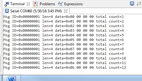
ERROR:
Error screenshots are attached for your reference.
Kindly advice to proceed further.
Thank you,
Sunil S
I have verified the CAN programs simple_rx.c and simple_tx.c from TivaWare version 2.1.4.178 using EK-TM4C123GXL launchpads and external CAN transceivers connecting with PB4 (CAN0RX) and PB4 (CAN0TX). Sequential messages are transmitted and received without error once every second as shown in the snippet below. My only conclusion is there is something wrong in your hardware setup or in your modified software. If you require additional help, you need to provide me more details of your code and your setup.
//***************************************************************************** // // simple_tx.c - Example demonstrating simple CAN message transmission. // // Copyright (c) 2010-2016 Texas Instruments Incorporated. All rights reserved. // Software License Agreement // // Redistribution and use in source and binary forms, with or without // modification, are permitted provided that the following conditions // are met: // // Redistributions of source code must retain the above copyright // notice, this list of conditions and the following disclaimer. // // Redistributions in binary form must reproduce the above copyright // notice, this list of conditions and the following disclaimer in the // documentation and/or other materials provided with the // distribution. // // Neither the name of Texas Instruments Incorporated nor the names of // its contributors may be used to endorse or promote products derived // from this software without specific prior written permission. // // THIS SOFTWARE IS PROVIDED BY THE COPYRIGHT HOLDERS AND CONTRIBUTORS // "AS IS" AND ANY EXPRESS OR IMPLIED WARRANTIES, INCLUDING, BUT NOT // LIMITED TO, THE IMPLIED WARRANTIES OF MERCHANTABILITY AND FITNESS FOR // A PARTICULAR PURPOSE ARE DISCLAIMED. IN NO EVENT SHALL THE COPYRIGHT // OWNER OR CONTRIBUTORS BE LIABLE FOR ANY DIRECT, INDIRECT, INCIDENTAL, // SPECIAL, EXEMPLARY, OR CONSEQUENTIAL DAMAGES (INCLUDING, BUT NOT // LIMITED TO, PROCUREMENT OF SUBSTITUTE GOODS OR SERVICES; LOSS OF USE, // DATA, OR PROFITS; OR BUSINESS INTERRUPTION) HOWEVER CAUSED AND ON ANY // THEORY OF LIABILITY, WHETHER IN CONTRACT, STRICT LIABILITY, OR TORT // (INCLUDING NEGLIGENCE OR OTHERWISE) ARISING IN ANY WAY OUT OF THE USE // OF THIS SOFTWARE, EVEN IF ADVISED OF THE POSSIBILITY OF SUCH DAMAGE. // // This is part of revision 2.1.3.156 of the Tiva Firmware Development Package. // //***************************************************************************** #include <stdbool.h> #include <stdint.h> #include "inc/tm4c123gh6pm.h" #include "inc/hw_can.h" #include "inc/hw_ints.h" #include "inc/hw_memmap.h" #include "driverlib/rom.h" #include "driverlib/can.h" #include "driverlib/gpio.h" #include "driverlib/interrupt.h" #include "driverlib/pin_map.h" #include "driverlib/sysctl.h" #include "driverlib/uart.h" #include "utils/uartstdio.h" #include "driverlib/timer.h" #include <stdint.h> #include <stdbool.h> #include "inc/tm4c123gh6pm.h" #include "inc/hw_ints.h" #include "inc/hw_memmap.h" #include "inc/hw_types.h" #include "driverlib/debug.h" #include "driverlib/fpu.h" #include "driverlib/gpio.h" #include "driverlib/interrupt.h" #include "driverlib/pin_map.h" #include "driverlib/rom.h" #include "driverlib/sysctl.h" #include "driverlib/timer.h" #include "driverlib/uart.h" #include "utils/uartstdio.h" #include "driverlib/pwm.h" //***************************************************************************** // //! \addtogroup can_examples_list //! <h1>Simple CAN TX (simple_tx)</h1> //! //! This example shows the basic setup of CAN in order to transmit messages //! on the CAN bus. The CAN peripheral is configured to transmit messages //! with a specific CAN ID. A message is then transmitted once per second, //! using a simple delay loop for timing. The message that is sent is a 4 //! byte message that contains an incrementing pattern. A CAN interrupt //! handler is used to confirm message transmission and count the number of //! messages that have been sent. //! //! This example uses the following peripherals and I/O signals. You must //! review these and change as needed for your own board: //! - CAN0 peripheral //! - GPIO Port B peripheral (for CAN0 pins) //! - CAN0RX - PB4 //! - CAN0TX - PB5 //! //! The following UART signals are configured only for displaying console //! messages for this example. These are not required for operation of CAN. //! - GPIO port A peripheral (for UART0 pins) //! - UART0RX - PA0 //! - UART0TX - PA1 //! //! This example uses the following interrupt handlers. To use this example //! in your own application you must add these interrupt handlers to your //! vector table. //! - INT_CAN0 - CANIntHandler // //***************************************************************************** //Structure for timer typedef struct { uint16_t uiOneSecCounter; }OBJ_DRV_TIMER; static OBJ_DRV_TIMER drvTimer; //***************************************************************************** // // A counter that keeps track of the number of times the TX interrupt has // occurred, which should match the number of TX messages that were sent. // //***************************************************************************** volatile uint32_t g_ui32MsgCount = 0; volatile uint32_t g_usyclk = 0; //***************************************************************************** // // A flag to indicate that some transmission error occurred. // //***************************************************************************** volatile bool g_bErrFlag = 0; volatile bool g_bRXFlag1 = 0; volatile uint32_t g_ui32Msg1Count = 0; volatile uint32_t g_ui32Msg2Count = 0; volatile uint32_t g_ui32Msg3Count = 0; tCANMsgObject sCANMessage; static uint32_t ui32MsgData; uint8_t *pui8MsgData; volatile bool g_bMsgObj3Sent = 0; tCANMsgObject g_sCANMsgObject1; tCANMsgObject g_sCANMsgObject2; tCANMsgObject g_sCANMsgObject3; uint8_t g_pui8Msg1[4] = { 0, 0, 0, 0 }; uint8_t g_pui8Msg2[5] = { 2, 2, 2, 2, 2 }; uint8_t g_pui8Msg3[6] = { 3, 3, 3, 3, 3, 3 }; uint8_t g_pui8Msg4[8] = { 4, 4, 4, 4, 5, 5, 5, 5 }; //***************************************************************************** // // This function sets up UART0 to be used for a console to display information // as the example is running. // //***************************************************************************** void InitConsole(void) { // // Enable GPIO port A which is used for UART0 pins. // TODO: change this to whichever GPIO port you are using. // SysCtlPeripheralEnable(SYSCTL_PERIPH_GPIOA); // // Configure the pin muxing for UART0 functions on port A0 and A1. // This step is not necessary if your part does not support pin muxing. // TODO: change this to select the port/pin you are using. // GPIOPinConfigure(GPIO_PA0_U0RX); GPIOPinConfigure(GPIO_PA1_U0TX); // // Enable UART0 so that we can configure the clock. // SysCtlPeripheralEnable(SYSCTL_PERIPH_UART0); // // Use the internal 16MHz oscillator as the UART clock source. // UARTClockSourceSet(UART0_BASE, UART_CLOCK_PIOSC); // // Select the alternate (UART) function for these pins. // TODO: change this to select the port/pin you are using. // GPIOPinTypeUART(GPIO_PORTA_BASE, GPIO_PIN_0 | GPIO_PIN_1); // // Initialize the UART for console I/O. // UARTStdioConfig(0, 115200, 16000000); } //***************************************************************************** // // This function provides a 1 second delay using a simple polling method. // //***************************************************************************** void SimpleDelay(void) { // // Delay cycles for 1 second // SysCtlDelay(16000000 / 3); } //***************************************************************************** // // The interrupt handler for the first timer interrupt. // //***************************************************************************** void Timer0IntHandler(void) { //char cOne, cTwo; // // Clear the timer interrupt. // TimerIntClear(TIMER0_BASE, TIMER_TIMA_TIMEOUT); // // Toggle the flag for the first timer. // //HWREGBITW(&g_ui32Flags, 0) ^= 1; // // Use the flags to Toggle the LED for this timer // // GPIOPinWrite(GPIO_PORTF_BASE, GPIO_PIN_1, g_ui32Flags << 1); drvTimer.uiOneSecCounter++; if(drvTimer.uiOneSecCounter > 1999) { drvTimer.uiOneSecCounter = 0; ui32MsgData++; CANMessageSet(CAN0_BASE, 1, &g_sCANMsgObject1, MSG_OBJ_TYPE_TX); (*(uint32_t *)g_pui8Msg1)++; } // // Update the interrupt status on the display. // // ROM_IntMasterDisable(); // cOne = HWREGBITW(&g_ui32Flags, 0) ? '1' : '0'; // cTwo = HWREGBITW(&g_ui32Flags, 1) ? '1' : '0'; // UARTprintf("\rT1: %c T2: %c", cOne, cTwo); //ROM_IntMasterEnable(); } void Timer0BIntHandler(void) { TimerIntClear(TIMER0_BASE, TIMER_TIMB_TIMEOUT); } //***************************************************************************** // // This function is the interrupt handler for the CAN peripheral. It checks // for the cause of the interrupt, and maintains a count of all messages that // have been transmitted. // //***************************************************************************** void CANIntHandler(void) { uint32_t ui32Status; // // Read the CAN interrupt status to find the cause of the interrupt // ui32Status = CANIntStatus(CAN0_BASE, CAN_INT_STS_CAUSE); // // If the cause is a controller status interrupt, then get the status // if(ui32Status == CAN_INT_INTID_STATUS) { // // Read the controller status. This will return a field of status // error bits that can indicate various errors. Error processing // is not done in this example for simplicity. Refer to the // API documentation for details about the error status bits. // The act of reading this status will clear the interrupt. If the // CAN peripheral is not connected to a CAN bus with other CAN devices // present, then errors will occur and will be indicated in the // controller status. // ui32Status = CANStatusGet(CAN0_BASE, CAN_STS_CONTROL); // // Set a flag to indicate some errors may have occurred. // g_bErrFlag = 1; } // // Check if the cause is message object 1, which what we are using for // sending messages. // else if(ui32Status == 1) { // // Getting to this point means that the TX interrupt occurred on // message object 1, and the message TX is complete. Clear the // message object interrupt. // CANIntClear(CAN0_BASE, 1); // // Increment a counter to keep track of how many messages have been // sent. In a real application this could be used to set flags to // indicate when a message is sent. // g_ui32Msg1Count++; // // Since the message was sent, clear any error flags. // g_bErrFlag = 0; } // // Check if the cause is message object 2, which is used for sending // message 2. // else if(ui32Status == 2) { // // Getting to this point means that the TX interrupt occurred on // message object 2, and the message TX is complete. Clear the // message object interrupt. // CANIntClear(CAN0_BASE, 2); // // Increment a counter to keep track of how many messages have been // sent. In a real application this could be used to set flags to // indicate when a message is sent. // g_ui32Msg2Count++; // // Since the message was sent, clear any error flags. // g_bErrFlag = 0; } // // Check if the cause is message object 3, which is used for sending // messages 3 and 4. // else if(ui32Status == 3) { // // Getting to this point means that the TX interrupt occurred on // message object 3, and a message TX is complete. Clear the // message object interrupt. // CANIntClear(CAN0_BASE, 3); // // Increment a counter to keep track of how many messages have been // sent. In a real application this could be used to set flags to // indicate when a message is sent. // g_ui32Msg3Count++; // // Set the flag indicating that a message was sent using message // object 3. The program main loop uses this to know when to send // another message using message object 3. // g_bMsgObj3Sent = 1; // // Since the message was sent, clear any error flags. // g_bErrFlag = 0; } // // Otherwise, something unexpected caused the interrupt. This should // never happen. // else { // // Spurious interrupt handling can go here. // } } //***************************************************************************** // // Configure the CAN and enter a loop to transmit periodic CAN messages. // //***************************************************************************** int main(void) { #if defined(TARGET_IS_TM4C129_RA0) || \ defined(TARGET_IS_TM4C129_RA1) || \ defined(TARGET_IS_TM4C129_RA2) uint32_t ui32SysClock; #endif pui8MsgData = (uint8_t *)&ui32MsgData; // // Set the clocking to run directly from the external crystal/oscillator. // TODO: The SYSCTL_XTAL_ value must be changed to match the value of the // crystal on your board. // #if defined(TARGET_IS_TM4C129_RA0) || \ defined(TARGET_IS_TM4C129_RA1) || \ defined(TARGET_IS_TM4C129_RA2) ui32SysClock = SysCtlClockFreqSet((SYSCTL_XTAL_25MHZ | SYSCTL_OSC_MAIN | SYSCTL_USE_OSC) 25000000); #else SysCtlClockSet(SYSCTL_SYSDIV_5 | SYSCTL_USE_PLL| SYSCTL_OSC_MAIN | SYSCTL_XTAL_16MHZ); #endif // // Set up the serial console to use for displaying messages. This is // just for this example program and is not needed for CAN operation. // InitConsole(); // // For this example CAN0 is used with RX and TX pins on port B4 and B5. // The actual port and pins used may be different on your part, consult // the data sheet for more information. // GPIO port B needs to be enabled so these pins can be used. // TODO: change this to whichever GPIO port you are using // SysCtlPeripheralEnable(SYSCTL_PERIPH_GPIOE); // // Configure the GPIO pin muxing to select CAN0 functions for these pins. // This step selects which alternate function is available for these pins. // This is necessary if your part supports GPIO pin function muxing. // Consult the data sheet to see which functions are allocated per pin. // TODO: change this to select the port/pin you are using // GPIOPinConfigure(GPIO_PE4_CAN0RX); GPIOPinConfigure(GPIO_PE5_CAN0TX); // // Enable the alternate function on the GPIO pins. The above step selects // which alternate function is available. This step actually enables the // alternate function instead of GPIO for these pins. // TODO: change this to match the port/pin you are using // GPIOPinTypeCAN(GPIO_PORTE_BASE, GPIO_PIN_4 | GPIO_PIN_5); // // The GPIO port and pins have been set up for CAN. The CAN peripheral // must be enabled. // SysCtlPeripheralEnable(SYSCTL_PERIPH_CAN0); // // Initialize the CAN controller // CANInit(CAN0_BASE); // // Set up the bit rate for the CAN bus. This function sets up the CAN // bus timing for a nominal configuration. You can achieve more control // over the CAN bus timing by using the function CANBitTimingSet() instead // of this one, if needed. // In this example, the CAN bus is set to 500 kHz. In the function below, // the call to SysCtlClockGet() or ui32SysClock is used to determine the // clock rate that is used for clocking the CAN peripheral. This can be // replaced with a fixed value if you know the value of the system clock, // saving the extra function call. For some parts, the CAN peripheral is // clocked by a fixed 8 MHz regardless of the system clock in which case // the call to SysCtlClockGet() or ui32SysClock should be replaced with // 8000000. Consult the data sheet for more information about CAN // peripheral clocking. // #if defined(TARGET_IS_TM4C129_RA0) || \ defined(TARGET_IS_TM4C129_RA1) || \ defined(TARGET_IS_TM4C129_RA2) CANBitRateSet(CAN0_BASE, ui32SysClock, 500000); #else CANBitRateSet(CAN0_BASE, SysCtlClockGet(), 500000); #endif // // Enable interrupts on the CAN peripheral. This example uses static // allocation of interrupt handlers which means the name of the handler // is in the vector table of startup code. If you want to use dynamic // allocation of the vector table, then you must also call CANIntRegister() // here. // // CANIntRegister(CAN0_BASE, CANIntHandler); // if using dynamic vectors // CANIntEnable(CAN0_BASE, CAN_INT_MASTER | CAN_INT_ERROR | CAN_INT_STATUS); // // Enable the CAN interrupt on the processor (NVIC). // IntEnable(INT_CAN0); // // Enable the CAN for operation. // CANEnable(CAN0_BASE); // // Initialize the message object that will be used for sending CAN // messages. The message will be 4 bytes that will contain an incrementing // value. Initially it will be set to 0. // ui32MsgData = 0; g_sCANMsgObject1.ui32MsgID = 0x1001; g_sCANMsgObject1.ui32MsgIDMask = 0; g_sCANMsgObject1.ui32Flags = MSG_OBJ_TX_INT_ENABLE; g_sCANMsgObject1.ui32MsgLen = sizeof(g_pui8Msg1); g_sCANMsgObject1.pui8MsgData = g_pui8Msg1; //Enable peripherals for timer SysCtlPeripheralEnable(SYSCTL_PERIPH_TIMER0); //Configure timer as periodic TimerConfigure(TIMER0_BASE, (TIMER_CFG_SPLIT_PAIR |TIMER_CFG_PERIODIC|TIMER_CFG_B_PERIODIC)); //load the timer A value TimerLoadSet(TIMER0_BASE, TIMER_A, SysCtlClockGet()/1024); TimerLoadSet(TIMER0_BASE, TIMER_B, 120000); // // Setup the interrupts for the timer timeouts. // IntEnable(INT_TIMER0A); TimerIntEnable(TIMER0_BASE, TIMER_TIMA_TIMEOUT); TimerEnable(TIMER0_BASE, TIMER_A); IntEnable(INT_TIMER0B); TimerIntEnable(TIMER0_BASE, TIMER_TIMB_TIMEOUT); IntMasterEnable(); g_usyclk = SysCtlClockGet(); // // Enter loop to send messages. A new message will be sent once per // second. The 4 bytes of message content will be treated as an uint32_t // and incremented by one each time. // while(1) { // // Print a message to the console showing the message count and the // contents of the message being sent. // UARTprintf("Sending msg: 0x%02X %02X %02X %02X", pui8MsgData[0], pui8MsgData[1], pui8MsgData[2], pui8MsgData[3]); SimpleDelay(); // // Send the CAN message using object number 1 (not the same thing as // CAN ID, which is also 1 in this example). This function will cause // the message to be transmitted right away. // // // Now wait 1 second before continuing // // // Check the error flag to see if errors occurred // if(g_bErrFlag) { UARTprintf(" error - cable connected?\n"); } else { // // If no errors then print the count of message sent // //UARTprintf(" total count = %u\n", g_ui32MsgCount); } // // Increment the value in the message data. // } // // Return no errors // return(0); }
here i am attaching the code . which is modified
In your file "can_code_transmit_modified" you also modified the CAN baud rate. In your file it is set to 500K baud. In the TI example "simple_RX", the baud rate is 100K baud. I modified your file by changing the baud rate to 100K baud (and deleted the redundant inclusion of some header files). The modified version now works properly with the TI example 'simple_RX".
Yes, I have attached a .zip file which contains two CCS projects, DK-CAN_simple_RX and DK-CAN_simple_TX. The only modification is that they use pins PE4 and PE5 for CAN0, just like the file you provided. Use the CCS function "File" -> "Import", "CCS Projects" and "Select archive file" to add these two projects to your workspace.
/cfs-file/__key/communityserver-discussions-components-files/908/DK_2D00_CAN_2D00_Simple.zip
Dear Bob Crosby ,
Thank you for sharing the code. I will test and update the status.