Part Number: TM4C123GH6PM
Other Parts Discussed in Thread: EK-TM4C123GXL
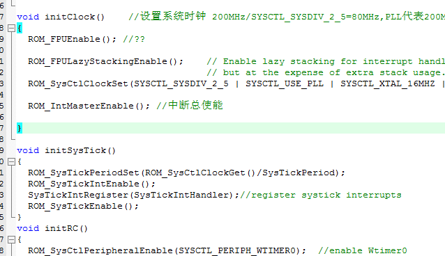
I want to measure 4ch PWM using capture mode of timer.Here is my configuration:
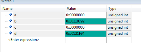
But somehow, I can't enter into the interrupt.Did I make some mistakes?
Original question:

Part Number: TM4C123GH6PM
Other Parts Discussed in Thread: EK-TM4C123GXL
I want to measure 4ch PWM using capture mode of timer.Here is my configuration:
But somehow, I can't enter into the interrupt.Did I make some mistakes?