This thread has been locked.
If you have a related question, please click the "Ask a related question" button in the top right corner. The newly created question will be automatically linked to this question.
Dear,
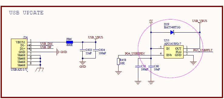
I want to use the USB Stick for Firmware update. The following is my circuit diagram. Boot code I used usb_stick_update in dk-m4c123g in TivaWare.
I have special attention to APP STAR Address 0x4800 in my Application Code and setting
However, when I press the button (Port F.4) while Power On, the program seems to have entered the Boot Code but there is no response. Please give advice .
Thanks & Best Regards
Leo Liao
I found that the usb_stick_update for DK-TM4C123G is using PL6 (USBDP) and PL7 (USBDM),
However, the MCU TM4C123GH6PZ I chose does not have PL6 and PL7.
I tried to modify the ConfigureUSBInterface() of TivaWare_C_Series-2.1.4.178\examples\boards\dk-tm4c123g\usb_stick_update
Changed from PL6.PL7 to PJ0.PJ1
Still not work, please give advice
Blue words are my modify content
Best Regards
Leo Liao
void
ConfigureUSBInterface(void)
{
//
// Enable the uDMA controller and set up the control table base.
// This is required by usblib.
//
ROM_SysCtlPeripheralEnable(SYSCTL_PERIPH_UDMA);
uDMAEnable();
uDMAControlBaseSet(g_sDMAControlTable);
//
// Enable the USB controller.
//
ROM_SysCtlPeripheralEnable(SYSCTL_PERIPH_USB0);
//
// Set the USB pins to be controlled by the USB controller.
//
ROM_SysCtlPeripheralEnable(SYSCTL_PERIPH_GPIOB);
ROM_SysCtlPeripheralEnable(SYSCTL_PERIPH_GPIOG);
ROM_GPIOPinConfigure(GPIO_PG4_USB0EPEN);
ROM_GPIOPinTypeUSBDigital(GPIO_PORTG_BASE, GPIO_PIN_4);
ROM_SysCtlPeripheralEnable(SYSCTL_PERIPH_GPIOJ);
ROM_GPIOPinTypeUSBAnalog(GPIO_PORTJ_BASE, GPIO_PIN_0 | GPIO_PIN_1);
ROM_GPIOPinTypeUSBAnalog(GPIO_PORTB_BASE, GPIO_PIN_0 | GPIO_PIN_1);
//
// Register the host class driver
//
USBHCDRegisterDrivers(0, g_ppHostClassDrivers, NUM_CLASS_DRIVERS);
//
// Open an instance of the mass storage class driver.
//
g_psMSCInstance = USBHMSCDriveOpen(0, MSCCallback);
//
// Initialize the power configuration. This sets the power enable signal
// to be active high and does not enable the power fault.
//
USBHCDPowerConfigInit(0, USBHCD_VBUS_AUTO_HIGH | USBHCD_VBUS_FILTER);
//
// Force the USB mode to host with no callback on mode changes since
// there should not be any.
//
USBStackModeSet(0, eUSBModeForceHost, 0);
//
// Wait 10ms for the pin to go low.
//
SysCtlDelay(SysCtlClockGet()/100);
//
// Initialize the host controller.
//
USBHCDInit(0, g_pHCDPool, HCD_MEMORY_SIZE);
}
Dear Ralph,
I found that the control polarity of the Power Switch (AP2141) I used is incorrect, the modified circuit as follow, I also tried to connect
USB0ID and USB0VBUS directly, Still fail, I put the waveform I measured on the web page, see if you can give advice. By the way, there is no short circuit between USB0VBUS and USB0ID (EK-TM4C1294XL)
EK-TM4C1294XL (Correct)
USB0VBUS and USB_DM
Our own schematic (Error)
USB0VBUS and USB_DM
Hi Ralph,
In the development board of DK-TM4C123G and EK-TM4C1294XL, There is an USB VBUS Load Switch TPS2052BDRB, you should know the purpose of this IC, Since our company has many AP2141WGs stocks, the function is the same as the TPS2052BDRB. Only the polarity of the control power output pin is different, so BJT is added for it.
Your previous suggested USB0VBUS and USB0ID need to be connected together, bypass the AP2141WG, I tried but fail
Finally, I attach my schematic and code, I hope you can come up with an effective solution.
void
ConfigureUSBInterface(void)
{
//
// Enable the uDMA controller and set up the control table base.
// This is required by usblib.
//
ROM_SysCtlPeripheralEnable(SYSCTL_PERIPH_UDMA);
uDMAEnable();
uDMAControlBaseSet(g_sDMAControlTable);
//
// Enable the USB controller.
//
ROM_SysCtlPeripheralEnable(SYSCTL_PERIPH_USB0);
//
// Set the USB pins to be controlled by the USB controller.
//
ROM_SysCtlPeripheralEnable(SYSCTL_PERIPH_GPIOB);
ROM_SysCtlPeripheralEnable(SYSCTL_PERIPH_GPIOG);
ROM_GPIOPinConfigure(GPIO_PG4_USB0EPEN);
ROM_GPIOPinTypeUSBDigital(GPIO_PORTG_BASE, GPIO_PIN_4);
ROM_SysCtlPeripheralEnable(SYSCTL_PERIPH_GPIOJ);
ROM_GPIOPinTypeUSBAnalog(GPIO_PORTJ_BASE, GPIO_PIN_0 | GPIO_PIN_1);
ROM_GPIOPinTypeUSBAnalog(GPIO_PORTB_BASE, GPIO_PIN_0 | GPIO_PIN_1);
//
// Register the host class driver
//
USBHCDRegisterDrivers(0, g_ppHostClassDrivers, NUM_CLASS_DRIVERS);
//
// Open an instance of the mass storage class driver.
//
g_psMSCInstance = USBHMSCDriveOpen(0, MSCCallback);
//
// Initialize the power configuration. This sets the power enable signal
// to be active high and does not enable the power fault.
//
USBHCDPowerConfigInit(0, USBHCD_VBUS_AUTO_HIGH | USBHCD_VBUS_FILTER);
//
// Force the USB mode to host with no callback on mode changes since
// there should not be any.
//
USBStackModeSet(0, eUSBModeForceHost, 0);
//
// Wait 10ms for the pin to go low.
//
SysCtlDelay(SysCtlClockGet()/100);
//
// Initialize the host controller.
//
USBHCDInit(0, g_pHCDPool, HCD_MEMORY_SIZE);
}