This thread has been locked.

If you have a related question, please click the "Ask a related question" button in the top right corner. The newly created question will be automatically linked to this question.

TM4C1294NCPDT: Capabilities of Internal USB PHY

Guru 55603 points
Other Parts Discussed in Thread: TM4C1294KCPDT

**Edit by forum moderator** This thread discussion was off-topic from original post and split into a new thread to better separate the individual issues.

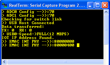
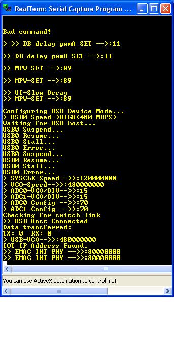
Did not the original USB library default USB2.0 standard, not the older USB1.1 standard? Are not the words Full and High speed (data transfer) synonymous meanings as they both relate to the USB clock source being 60mHz? To me the word full is all that high can ever be, when low is at the opposite end of the spectrum, lol.

Perhaps TI could have chosen some other word to differentiate the two data transfer methods more clearly. I too was bewildered by the double meaning when reviewing the updated USB library. Thanks for pointing out internal PHY is to use FULL speed library calls and assume those same calls support USB2.0 standard protocol?

  • Hi BP101,

    I agree that full vs high speed is very confusing terminology!

    That said, it wasn't our choice to name it that way, the naming is straight from USB specs: https://en.wikipedia.org/wiki/USB#USB_2.0

    So we are just following industry standards, as confusing as they are... I wonder what will be after 'SuperSpeed+', maybe HyperSpeed? LightSpeed? :)

    Yes the same calls can support USB 2.0 if an external PHY is used and high speed is properly configured.

  • Hi Ralph,

    Ralph Jacobi said:
    Yes the same calls can support USB 2.0 if an external PHY is used and high speed is properly configured.

    So your saying the internal PHY is USB2.0 standard? Confusing since bulk device initiate calls USBDCDINIT() and tests for ULPISupport (FS/HS) also moves on to check for eUSBModeDevice which is neither FS or HS. Hence adds to the confusion if internal PHY supports USB2.0 speeds. Still have no idea what USB version when FEATURE_ULPI_NONE. Seemingly internal PHY is USB2.0 yet some computers BIOS still support USB1.1 peripherals or clients.  

  • Hi BP101,

    Huh? I was saying the same TivaWare API SOFTWARE calls support 2.0. Not the silicon. That's why an external PHY is needed to do 2.0...
  • Hi Ralph / Charles,

    I was referring to the silicon supporting 2.0 speeds 480Mbps at the USB port plug as do computers after 4/2K. Yesterday discovered USB library labels parts of bulk device driver calls are 2.0 standard. Also discovered it did not directly configure the two device endpoints via USBEndPoitConfigSet() for the composite bulk device driver. If you try to follow the calls that should configure the hardware for the endpoints via USBEndPointConfigSet() you end up at a dead end with only a pointer being set, no call to directly configure the endpoints. So to believe the internal PHY only supports USB 1.1 speeds (12Mbps) seems incorrect.

    Perhaps the HS/FS assignment must be doing other hardware configurations namely for an external PHY, not that MCU don't support 480Mbps on the internal PHY endpoints. Otherwise the datasheet and USB library (foot notes) fails to make any such point clear, questionably MCU only supports USB1.1 speeds via internal PHY.

    I added the calls below after the pointers were linked to the composite bulk structs for the two named end points. I could only see the DMA was configured but no flags were being set. The entire project relies on some hidden default library configuration (interrupts) makes near impossible to find track or fix bugs. The process that configures the endpoints silicon hardware is poorly documented in the bulk device example.

    The hex decode (below) is same for EP1 as device IN/OUT. Oddly when the device is plugged in to host the status returned by endpoints event callback loops twice (error). That error loop occurs even if points are not configured and the message value (ui32MsgValue) is never returned in the status of USB_EVENT_ ~. Oddly the same status errors occur when ever random endpoint disconnects while the interface (end point 0) remains intact to/with the host. The loop errors may be occurring during the hidden library interrupts handling that magically occurs in background handlers, I hate magic tricks. lol

    USBDBulkCompositeInit:

        // Set the default endpoint and interface assignments.
        // EP1=0x00000010
        psInst->ui8INEndpoint = DATA_IN_ENDPOINT; // 512 byte packet ui32EndPoint
        psInst->ui8OUTEndpoint = DATA_OUT_ENDPOINT;// 512 byte packet ui32EndPoint
        psInst->ui8Interface = 0;]
    
    Added after USBDBulkInit();
    
        /* Configure USB0 IN endpoint, zero is reserved.
         * USB_EP_2,USB_EP_3,USB_EP_4,USB_EP_5,USB_EP_6,USB_EP_7 */
        USBDevEndpointConfigSet(USB0_BASE, USB_EP_1 , 512,
                                (USB_EP_MODE_BULK|USB_EP_AUTO_CLEAR));
        /* Configure USB0 OUT endpoint */
        USBDevEndpointConfigSet(USB0_BASE, USB_EP_1 , 512,
                                (USB_EP_MODE_BULK|USB_EP_AUTO_SET));


  • Ralph Jacobi said:
    That's why an external PHY is needed to do 2.0...

    Huh? So your believing TI went backwards, used silicon designed 1996 for an MCU released well after April 2000?  That makes no logical sense after seeing USB 2.0 standard adopted world wide in most every hardware on the market.

  • Hello BP101,

    This discussion is getting very off-topic, if you want to continue it, please open a new thread on the topic.

  • Hi Charles,

    Charles stated the internal PHY supports FULL speed only.

    Released in January 1996, USB 1.0 specified data rates of 1.5 Mbit/s (Low Bandwidth or Low Speed) and 12 Mbit/s (Full Speed).

    My computer Award BIOS does not support USB1.1 so how is a USB2.0 BIOS. That is sort of the point, if the TM4C1294 PHY is compatible with USB1.1 protocol. How on earth is USB library properly configuring end points for USB2.0 protocol changes to maintain compatibility with modern computers? Seemingly the USB library PHY device configuration maintains MARGINAL backward compatibility with USB2.0 protocol changes.

    Likewise the bulk device DCD endpoints are neither configured for FULL or High speed. We only get 256KBPS packet transfers according to past test of bulk client, seemed fast enough at first. That is not Full Speed transfer rate, rather low speed 1.5Mbits, internal PHY connected to remote USB2.0 host. Now expecting USB 2.0 (12Mbit) speed from the internal PHY with bulk device client. 

    Datasheet specified 480MBPS for an external PHY was presented as an option to interface USB0 peripheral with external HUB chips in my mind. No wonder we are having odd problems with random bulk data transfer end pipe corruptions when NVIC gets real busy!


  • Appears the internal PHY resets 480MPS as reported by the USB library call to check the configured device/host speeds prior to initialization completion. After that it ends up in Full Speed mode.

       /* Get the configured PHY transfer speed  */
        //ui32USB0DevSpeed = USBHostSpeedGet();
        ui32USB0DevSpeed = USBDevSpeedGet(USB0_BASE);
    
        /* Report the speed of USB0 PHY endpoints */
        if(ui32USB0DevSpeed == USB_HIGH_SPEED)
        {
            UARTprintf("> USB0-Speed->HIGH(480 MBPS)\n");
        }
        else if(ui32USB0DevSpeed == USB_FULL_SPEED)
        {
            UARTprintf("> USB0-Speed->FULL(12 MBPS)\n");
        }
        else
        {
            UARTprintf("> USB0-Speed->LOW(1.5 MBPS)\n");
        }
  • Oddly USB0 defaults High Speed (above post), after configuration descriptor is sent EP1 it down shifts to Full Speed. The device descriptor note (below) states USB 1.1 infers USB2.0 and PHY should be faster than 12MBPS.  Hence my confusion that USB0 speed is not being set by a call to configure EP1 speed and the descriptor fails to set HS. It is widely believed USB0 peripheral PHY on the EVM was designed for todays USB2.0 standards and not specifically USB 1.1 post 1998.  My host USB2.0 computer connects to target device PHY, logically it seems could be made to run High speed instead of Full Speed via the internal PHY.

    Otherwise USBHostEndpointSpeed() allows us to set the speed of the HOST control endpoint 0 and or other configured endpoints besides 0.

    TM4C1294 USB 2.0 protocol is not what the computer industry projects to the public being much faster than USB 1.1. Descriptor BCD seems to determine the device connection speed and 0x200 made no difference over that of 0x110. So we now want to try LS configuration, should be simple as changing BCD 0x100 in the device descriptor field.   

    The bcdUSB field reports the highest version of USB the device supports. The value is in binary coded decimal with a format of 0xJJMN where JJ is the major version number, M is the minor version number and N is the sub minor version number. e.g. USB 2.0 is reported as 0x0200, USB 1.1 as 0x0110 and USB 1.0 as 0x0100.


  • Truth of the matter seems to indicate Tivaware BULK stream end pipe 1 had only 64 byte packets. Full Speed requires much smaller packet sizes (below text) . Yet I re-configured stream 1 end pipes/descriptor for 512 bye packets and it worked even better than 64 byte packet length, Full Speed mode. However the BCD change 0x0200 (USB2.0) in above post BULK descriptor made no difference to the device host connection speed up shifting to HS mode. Seemingly DCD devices can not run in LS mode (1.5Mbps) even for testing purposes.

    Yet FS mode data throughput improved with 512 byte packets in the end point 1 configuration. So it seems the HOST end point can accept and digest packet sizes >64bytes reducing target load of ring buffer transfers via DMA. Likely since typical USB2.0 computer PHY are not being speed restricted in the same way TM4C1294 has been restricted to FS mode via internal PHY. I would suspect same true of all end pipes DCD configurations in Tivaware devices restricting internal PHY to FS mode or 64 byte packets.


    Bulk Transfers:
    ◾Used to transfer large bursty data.
    ◾Error detection via CRC, with guarantee of delivery.
    ◾No guarantee of bandwidth or minimum latency.
    ◾Stream Pipe - Unidirectional
    ◾Full & high speed modes only.

    Bulk transfers are only supported by full and high speed devices. For full speed endpoints, the maximum bulk packet size is either 8, 16, 32 or 64 bytes long. For high speed endpoints, the maximum packet size can be up to 512 bytes long. If the data payload falls short of the maximum packet size, it doesn't need to be padded with zeros. A bulk transfer is considered complete when it has transferred the exact amount of data requested, transferred a packet less than the maximum endpoint size, or transferred a zero-length packet.
  • Hello BP101,

    I split this topic out of our other customers thread since you want to continue discussion. I linked this post to that thread for any interested parties to continue following along.

    As you've identified, yes to follow USB standards we use 64 byte packets for FS mode. You can improve the throughput the way you describe but as it is no longer following USB standard you would have to do that in a close loop system that never actually interacts with a USB standard host.

    A USB2.0 compliant computer PHY would request device information on connection and the TM4C would reply back that it is a full speed device and thus the computer will limit speeds and use 64 byte packets unless the TM4C is configured for HS mode with an external PHY to drive the high speed communication.

    As far as the whole topic of USB2.0 with TM4C, our datasheet lists repeatedly that high speed operation or 2.0 operation requires an external PHY.

    "USB 2.0 Controller OTG/Host/Device with optional high speed using external PHY through ULPI interface"

    "USB 2.0 high-speed (480 Mbps) operation with the integrated ULPI interface communicating with an external PHY"

    On block diagram: "USB OTG (FS PHY or ULPI)"

    While we may agree to disagree on this subjective topic of clarity of statements, I would say we did our job to properly label the capabilities of the device and outlining what is and isn't met from a 2.0 high speed specification standpoint.
  • Ralph Jacobi said:
    A USB2.0 compliant computer PHY would request device information on connection and the TM4C would reply back that it is a full speed device and thus the computer will limit speeds and use 64 byte packets unless the TM4C is configured for HS mode with an external PHY to drive the high speed communication.

    For the sake of the CDC discussion this thread de-merged from, notes the following counter points;

    1. The USB2.0 computers after 1999 are designed to operate with an attached device in HS mode, do not limit USB ports via 64 byte packets as Tivaware USB library has done. 

    2. Would seem the throttled down PHY Full Speed (12MBPS) is not in full USB2.0 compliance as it relate to remote Host connections. Disclaimer follows;

    The TM4C1294KCPDT USB controller operates as a full-speed or low-speed function controller during point-to-point communications with USB Host, Device, or OTG functions.

    3. Device mode can not drop below Full Speed, though I'd like to test Low Speed device mode and may correct issues with random unexplained Suspend descriptor occurrence. 

    4. Also datasheet below disclaimer is not typical understanding of USB2.0 High Speed device modes post 1999 computers employ and confuses the device connection subject.  

    ■ USB 2.0 high-speed (480 Mbps) operation with the integrated ULPI interface communicating with an external PHY

    5. Link state signaling and or current detection on VBUS package pin and register control of current consumption has little to no noise immunity (Full Speed) to PWM driven devices.

    ■ Link Power Management support which uses link-state awareness to reduce power usage.

    6. What may seem like Full Speed USB2.0 device compliance is actually USB library throttled down packet transfers to comply with a limited PHY. Those limited 64 byte packets are unexpected by computers manufactured after1999 that can easily crunch 512 byte packets. Well anyway they remain 512k packets since the device Endpoint PIPE is configured so and the Host is not rejecting the larger packet.

        /* Configure USB0 OUT endpoint for 512 byte max packet size,
         * EP_0 reserves first 16 Bytes for control port data.
         * USB_EP_2,USB_EP_3,USB_EP_4,USB_EP_5,USB_EP_6,USB_EP_7 */
        USBDevEndpointConfigSet(USB0_BASE, USB_EP_1 , 512,
                                (USB_EP_MODE_BULK|USB_EP_AUTO_CLEAR));//USB_EP_AUTO_REQUEST (EPn Host)
        /* Configure USB0 IN endpoint for 512 byte Max packet size */
        USBDevEndpointConfigSet(USB0_BASE, USB_EP_1 , 512,
                                (USB_EP_MODE_BULK|USB_EP_AUTO_SET));

    7. Lets give the USB FIFO more room to improve through put of Ring Buffer handling of packets:

        /* Configure EP_1 (RAM) IN/OUT start address, 64/576 bytes into FIFO
         * Must be on 8 byte boundary */
        USBFIFOConfigSet(USB0_BASE, USB_EP_1, 64, USB_FIFO_SZ_512, USB_EP_DEV_OUT); 
        USBFIFOConfigSet(USB0_BASE, USB_EP_1, 576, USB_FIFO_SZ_512, USB_EP_DEV_IN); 

    8. Lastly lets improve DMA handling of packet interrupts leveraged via Ring Buffer 512 byte transfers made to our composite devices via other USB library paths/methods. Note 8 total configured device endpoints exist, e.g. (EP1-EP7) are unidirectional streams and support large packets, EP0 remains 64 byte control packets and is not configured below or above points. 

        /* Configure IN endpoint DMA channle mode 1 typically used for transfers that
         *  span multiple packets and do not require interrupts between packets. */
        USBEndpointDMAConfigSet(USB0_BASE, USB_EP_1,
                                USB_EP_DEV_IN | USB_EP_DMA_MODE_1 | USB_EP_AUTO_SET);
        /* Configure DMA channle mode 1 for OUT endpoint 1 */
        USBEndpointDMAConfigSet(USB0_BASE, USB_EP_1,
                                USB_EP_DEV_OUT | USB_EP_DMA_MODE_1 | USB_EP_AUTO_CLEAR);
  • Hello BP101,

    You should read the USB 2.0 specification again.

    "The USB defines the allowable maximum bulk data payload sizes to be only 8, 16, 32, or 64 bytes for full-speed endpoints and 512 bytes for high-speed endpoints."

    The same is said for other endpoint types, except for Isochronous which is 1,023 bytes.
  • I don't always believe what I read on the internet as being gospel especially from USB IN A NUTSHELL. It makes a good attempt to confuse a Bulk descriptor max packet with Control EP0 64 byte limitation. You have to ask why on earth would a 12MBPS pipe stream be limited to 64 byte packet or frame and seemingly was taken from part of the 1.0 specification. Logically If the host side composite driver could not accept 512k packet it would NAK the target and not transfer any packets even STALL the end pipe.

    Logically 12MBPS is above lowest Ethernet 10MBPS speed and transfers 512 byte packets in a heart beat. Device stream pipe protocol mentions ACK/NAK/STALL under conditions the FIFO keeps filling without padding down the remaining space. Try it yourself add USB ring buffer calls USBBufferWrite() to replace echo character handlers. USB Buffer Write points to the buffer space defined in the composite (usb_bulk_struct.c), a magic trick anyone can appreciate!

  • Hello BP101,

    The line I posted is DIRECTLY out of the USB 2.0 spec provided on USB.com. I don't make the specifications, I follow them. This has nothing to do with third party sites or other sources, this is the USB standard as written and released. I understand with your thoughts, but we don't have any control on how USB 2.0 was specified.

  • Agree the public was deceived by USB2.0 to think they were getting more speed by upgrading USB1.1 mother boards. Fact later discovered here in forum USB1.1 was the same as USB2.0 Full Speed 12MBPS never changed by upgrading computers. At least that is my perception  challenged by actual observations that defy the notion less is more.

    Oddly the Bulk Device descriptor configured 1024 byte packets and EP1 the same size does not post a Windows client exception.  If the USB2.0 defined descriptor (0x0200) packet size was deceptively reduced during Plug & Play mangers detection. Seemingly it would notify that an error occurred during enumeration or that it was unable to enumerate the device. Neither of which is occurring thus further collaborates even the larger 1024 packet size is acceptable to (lmusbdll.lib) FIFO handlers.

    Based on those observations the Bulk streaming pipe FIFO is not limited to 64byte or even 512 byte packets..  

    https://www.beyondlogic.org/usbnutshell/usb3.shtml#USBProtocols