This thread has been locked.

If you have a related question, please click the "Ask a related question" button in the top right corner. The newly created question will be automatically linked to this question.

TM4C1294NCPDT: ROM Bootloader on TIVA TM4C1294NCPDT controller over sflash does not work

Part Number: TM4C1294NCPDT
Other Parts Discussed in Thread: UNIFLASH, EK-TM4C129EXL, EK-TM4C1294XL, EK-TM4C123GXL

I am using TIVA TM4C1294NCPDT controller on a custom board. I have UART0 connected to UART of an embedded linux board. During normal OS operation, I am able to invoke the ROM bootloader by calling ROM_UpdateUART() to update firmware using sflash utility. This method works fine as long as I have some firmware already on the device. 

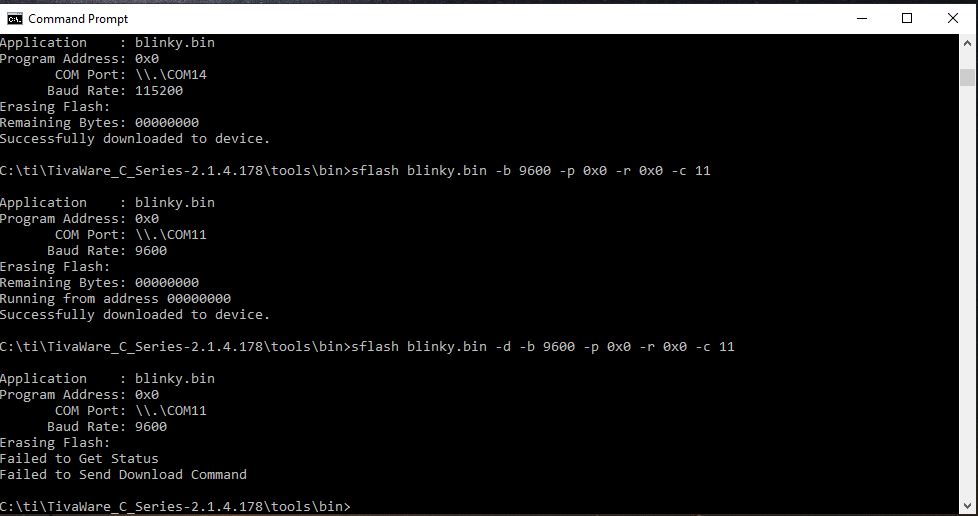
I want to program virgin devices using sflash. To test this, I erased the flash and confirmed over JTAG that 0x0 and 0x4 locations read 0xFFFF_FFFF and that BOOTCFG register is 0xFFFF_FFFE. On a blank device, I expect the device to stay in ROM bootloader looking for packets over UART. However, when I run sflash, I get the 'erasing' chip message and nothing after that. 

I have also noticed that when the bootloader is invoked using ROM_UpdateUART(), if the firmware update is interrupted and restarted, the device resumes the firmware update and continues successfully. However, if after interrupting, power is cycled, then the update does not resume. The symptoms are similar to the failure mode mentioned above in the blank chip case. Can the gurus confirm if the ROM bootloader and sflash combo is resistant to power interruptions? Does the ROM bootloader write 0x0 and 0x4 locations at the end of the update or before?

Also, any ideas on why sflash and ROM bootloader do not work when device is blank? How do I go about debugging the ROM bootloader?

Thanks in advance for your time and inputs,

Rajah

  • Hi Rajah,

      After you run sflash and get the 'erasing' chip message, did you have a chance to connect using JTAG and see what has actually happened? Meaning do you see anything in the flash either in full or partially programmed? Can you please also try on the LaunchPad? Will you see any different result? I currently don't have the launchPad with me. I will try myself tomorrow too.

      Regarding the power cycle in the middle of the bootloading, I suspect that the flash was already partially programmed. When you power cycle again, the ROM bootloader sees the 0x0 and 0x4 with non-F values without knowing the bootloading was interrupted. If your bootloading procedure can be subjected to power loss then I will suggest you use the flash based bootloader. The flash based bootloader can be enabled to include checksum. Not only the 0x0 and 0x4 are checked if the application is present but also the CRC of the firmware image after the bootloading. If the CRC is incorrect, the firmware update will be pending again. 

  • Thanks for the input Charles. I will check over JTAG and let you know. For the power interruption case, I just assumed that the 0x0 and 0x4 locations would be programmed last (at the end of firmware update). However, based on what you tell me, it looks like that is not the case. I wanted one the gurus like you to confirm this. 

    In the long run, I want to more to a flash based bootloader with CRC and hardware pin to force to boot.

    WRT the blank chip programming, I am correct in assuming that a blank device will listen to firmware packets over UART right over the ROM bootloader right? I want to use this option in production (for eaxample to load the flash bootloader).

    Thanks,

    Rajah

  • Hi Rajah,

      Your understanding is correct. If the flash is blank, then the ROM bootloader will listen to firmware packets over UART. 

      Please also take a look at this below post which explains the order of different communication interfaces the ROM bootloader will listen for firrmware update packets. 

    https://e2e.ti.com/support/microcontrollers/other/f/908/t/621470?TM4C129-ROM-Bootloader

  • Hello Rajah & Charles. 

    Rajah, as Charles may verify, at the past I had also confronted with a similar issue and so I decided to built my own bootloader, based on the TIVA libraries and ignore ROM bootloaders. What I did was to use UNIFlash over JTAG, for every new manufactured board with a TM4C1294NCPDT on board, and load my bootloader. So after the next boot, board waits for receiving firmware data to load in FLASH, in my case at 0x8000, from any interface I choose to do it from inside my bootloader firmware. But the bootloader program itself, when boots and before starts waiting, checks at an EEPROM address of your choice for an FF or 0x0 or 0x1. If it finds it to be 0xFF or 0x0 goes to the waiting mode and waits for new firmware. After new firmware is loaded, bootloader goes to that EEPROM address and writes an '1' and then causes a reboot. Now board boots and bootloader finding an '1' at the EEPROM check-address, jumps directly to the main firmware boot at 0x8000. [Linker file RAM address at the snowflake link file and RAM  address at the main body of your firmware need to have 0x8000 written instead of 0x0004/0x0000. You can play with caution at will with the address space usage for the locations of the bootloader firmware and the main firmware] 

    Then, whenever you need a new firmware update, you just go and write a '0' at the specific EEPROM address either with a command from inside your main running firmware or  a pin usage that is also checked from inside your main firmware, and after next boot your board will again enter the bootloader firmware update waiting mode.

    I hope this can help. Good luck,

    John

  • Hi John,

      Thanks for providing additional ideas to the OP. 

    Hi Rajah,

      I run both the sflash and LM flash programmer and I do see that without the flash first erased, the ROM bootloader will not continue. I think the reason is that the ROM bootloader is checking if 0x0 and 0x4 are non-F. If there is already an application present at 0x0 then it will just run the application.

  • Thanks for your input John. I have a bootloader that I can use with my product. My product has an embedded linux micro and the TIVA chip. I would like to use the embedded linux to program my Boot and OS using the ROM bootloader for the first time. After the first time, I can just use my bootloader in flash. The programming of the chip will happen just before EOL testing when the product is fully assembled. Reaching the JTAG port is going to be tough. We also want to remote the JTAG header once we ramp up production. Adding a person to connect and program in manufacturing will also add cost. I just assumed the bootloader in ROM worked. If the ROM bootloader does not work, we have to change the production workflow to use JTAG.

  • Hi Charles,

    I got hold of a EK-TM4C129EXL Rev A board and used LM flash to erase the chip. Once the chip was erased, I power cycled the board and tried to use sflash to program OS to the flash. I have connected my USB to serial adapter to UART0 Tx and Rx to the board (PA0 and PA1, pin numbers 74 and 76 on bread board connector, http://www.ti.com/lit/ml/spmz862/spmz862.pdf, page 19 Table 2-4). I used Uniflash programmer to erase my chip and blank checked it. I then power cycled the board and tried to run sflash.

    ./sflash my.bin -d -b 9600 -p 0x0 -r 0x0 -c /dev/tty.usbserial

    I have scope probes connected to PA0 and PA1. I can see two bytes sent on the serial line PA0, but I don't see anything on PA1.

    I added some prints to sflash source code and see that I don't get an ACK from the MCU. So looks like the chip is not in BootROM or boot ROM did not detect the bytes sent.

    @Charles, is there any way to tell if the device is in ROM bootloader or any GPIO pins I can probe to get details on the BootROM state machine?

    Thanks,

    Rajah

  • Hi Rajah,

      Can you try to remove the -d switch and see if it makes a difference?

      This post provides some more details. 

    https://e2e.ti.com/support/microcontrollers/other/f/908/p/760322/2809102?tisearch=e2e-sitesearch&keymatch=disable%20auto%20baud%20support#2809102

  • Hi Charles, thanks for the quick response. When I do not include the -d option, then I dont see any packets being sent on the scope. The command tries for a while and gives up with a fail message (Failed to synchronize with board.). If the -d command is included, I am able to see packets on Tx lines. In fact, when I use the ROM_UpadateUART() API to bootload, I use the same command (with the -d option) and everything works. 

    Is there anyway to tell if we are in the ROM bootloader?

    Thanks,

    Rajah

  • Hi Rajah,

      I'm getting the opposite results from yours. Please see below image. My flash is fully erased before invoking the sflash. Without -d it will program but with the -d it will fail. I'm running on a Windows machine. I'm not sure if you modify the sflash source code. Do you have a Windows machine that you can try and invoke the existing bin/sflash.exe. Without the -d it means it will enable the auto baud rate. This allows the MCU to find out the baud clock frequency from the host machine. With the -d, you disable the auto baud rate detection. You specify 9600 as your baud clock. However, I don't think the default baud clock from the MCU is 9600. I tend to think it is 115200 although I'm not 100% sure. If you want to include -d, please try 115200 and see if you get different result. 

    It is really hard to gain visibility into the MCU when the MCU is still booting running the ROM code. There is no GPIO signals or anything that indicate as such. 

  • Hi Charles, thanks for taking the time to try it out on your end. I found a windows machine and tried the commands you have above in the screenshot. In my case, the only difference is the com port, I am on COM15. Without the -d option, I dont see any output after the command. With the -d option, after Erasing flash message, I get a "Failed to send download command" after about a minute of trying. I even have the same version of Tivaware. For the EK-TM4C129 board, can you confirm that pin 74 and 76 are the pins to use on the breadboard connector?

    Thanks,
    Rajah

  • Hi Rajah,

      Do you have other EK-TM4C1294XL boards to try or you only have one launchPad? I tried on another launchPad I have which produces the same result. I only have two EK-TM4C1294XL boards with me. I even tried on a EK-TM4C123GXL board and it also programs only without the -d. I think it makes sense to enable the auto baud rate. The ROM bootloader has no way of knowing what baud rate the host machine will be using. When the host machine enables the auto baud rate, it will first send some train of 0x5 or 0xA pulses. These clock pulses allows the ROM bootloader to determine the proper baud rate to configure its UART. With that said, I don't understand why your board doesn't work like mine. I hope you have other boards to try. If you have other boards and they consistently show the same behavior as the first one, then I can spend some more time and also discuss with my colleague. Unfortunately, my two other colleagues supporting TM4C are both out of office at the moment. I won't be able to pick their brain until next week. 

  • Hi Rajah,

      Pin 74 and 76 on the breakout boards are the PA0 and PA1 so they are correct to probe. While looking at the schematic I see this note. I wonder if you changed the jumper setting before. Please revert to the original jumper position. 

  • I only have the EK-TM4C1294XL board, I dont have a launch pad.

  • Let me check the jumpers and get back to you.

  • The EK-TM4C1294XL is the launchPad. 

  • Hi Charles, thanks for your inputs and time. I checked the jumpers, they were fine too. I finally narrowed down the issue to the USB-UART dongle I was using. I cannot explain why, but it seems to work fine when showing my debug messages for running code, but it does not seem to work when using for bootloading. If I had to guess, the issue may be related only Tx on the UART to USB being broken (since Rx works fine for debug messages). I changed the dongle to another model/brand that I had around and it worked on first try. Thank you very much for your help. I had to remove the -d option when using the ROM bootloader. I have since ported the flash bootloader to my application to have some more control. So now I am all set to use the ROM bootloader to load my flash bootloader in manufacturing and then I am able to use my flash bootloader to update code.