This thread has been locked.

If you have a related question, please click the "Ask a related question" button in the top right corner. The newly created question will be automatically linked to this question.

TM4C123GH6PZ: Noise on VDDC pin

Part Number: TM4C123GH6PZ
Other Parts Discussed in Thread: EK-TM4C123GXL

Hi,

I have custom board based on TM4C123GH6PZ. I am having programming issue. 

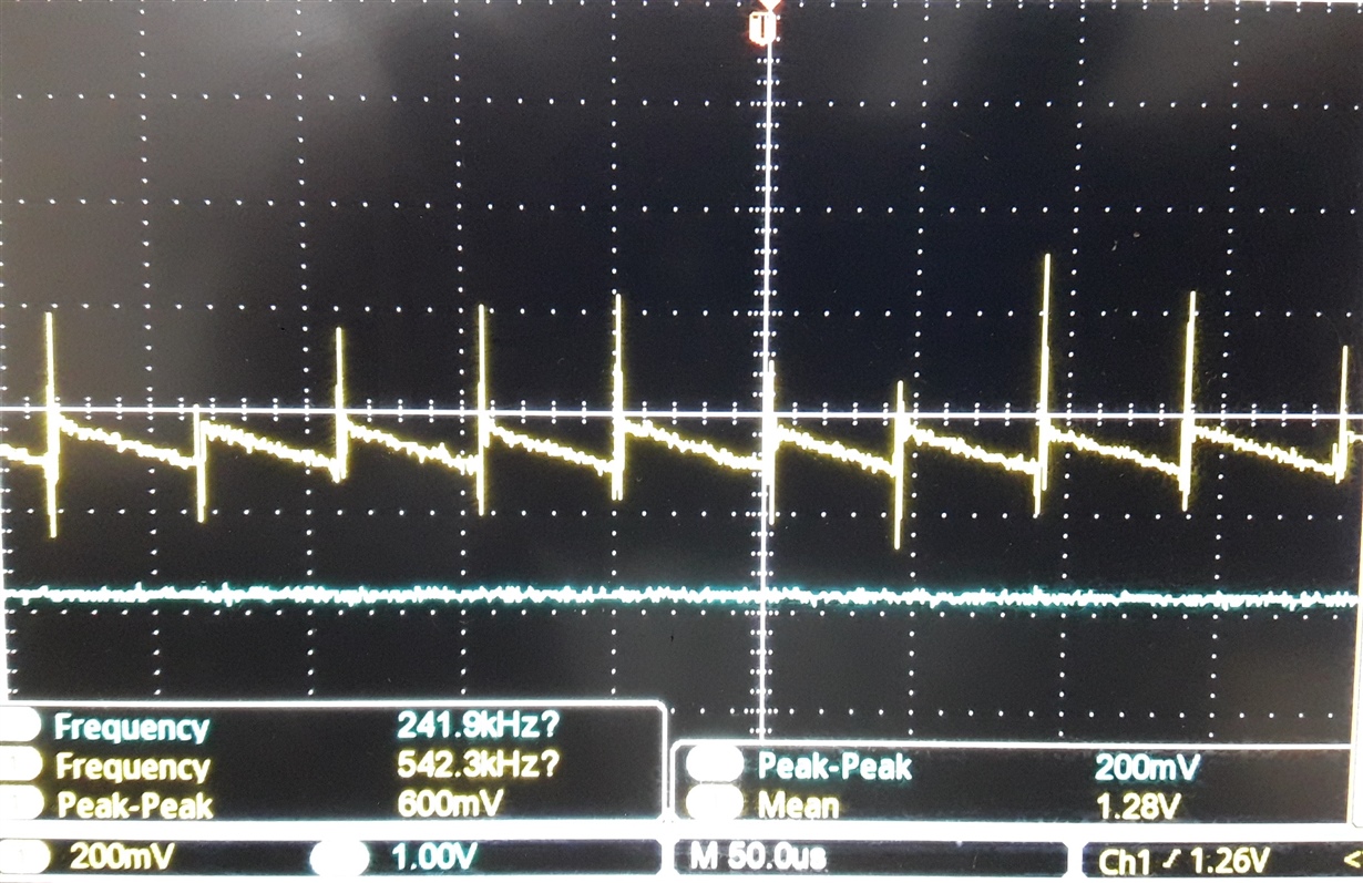
After checking in details I found so much noise on VDDC pin. I attached signals screenshot for your reference.

I already connected 0.1uF and 4.7uF ceramic capacitor to these pins. I checked noise on 3.3v dc. it is showing upto 80-100mV.

If I checked on VDDC pin. It is showing upto 600mV for 1.2V which is too much.

Why so much noise is coming on VDDC pin?

Thanks and regards,

Somnath Barge

  • Greetings,

    Feel your pain - yet might (added) key data increase diagnostic effectiveness?

    • had this custom board "ever" worked?    If so - what occurred just prior to "programming issue?"
    • "programming issue" is undefined - detailing is required.   We know "nothing" of your "method and/or program device" in addition to, "What's meant by "issue!"
    • you note, "So much noise on VDDC" - yet do not describe your "basis" for that statement.    (i.e. have you measured VDDC upon a '123 based "LPad" - & found that "much less noisy?"   Without such a "comparative reference" - your judgement (much noise)  may prove faulty...
    • under what MCU operating conditions was this measurement made?    (Again - "programming issue" (may) suggest, "No program loaded" - yet that's not certain due to the "issue's vagueness.")
    • are the VDDC caps placed as close as possible to the VDDC pins - are they of high quality (new? - ceramic is a good choice)
    • is the ground return of these VDDC caps proper?   Short & sufficiently wide pcb traces insure best results

    Much like a courtroom - sufficient (& proper) evidence must be gathered - then methodically weighed - to encourage the best conclusion.

  • CB1 is right on target with his answer. In addition, you might look at section 3.5 of the TM4C123 System Design Guidelines

  • Hi CB1,

    Sorry for your confusion. 

    Programming issue refers to problems raised dur ing flash programming of TM4C123G.  Please check attached "error.jpg".

    • First I manufactured 2 boards. But that two boards didn't found any such problem. Therefore I didn't checked voltage on VDDC pin. But now I assembled more boards. Some boards programmed (using LM Flash Programmer through UART). But some boards are getting error.
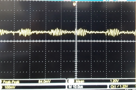
    • I already checked noise on VDDC pin in TM4C123G Development board. Please check attached "Dev board noise.jpg". It is about of 84-100mv. That's why I noted "So much noise on VDDC"
    • VDDC caps are placed close to the VDDC pins but are placed on one side only. Please check attached "vddc cap.jpg".
    • I used X5R ceramic capacitor purchased from authorized distributor.
    • One observation I found is that noise is less if I used Tentalum capacitor instead of ceramic capacitor. For ceramic capacitor, noise is around 600mv while for tentalum capacitor, noise is around 240mv.
    • Again one more observation, if noise is less on VDDC pin(240mv) then no problems found at the time of flash programming microcontroller through LM Flash programmer.
    • Also if noise is more then there is more chance of misbehavior of controller. Am I right?

    I thing flash programming problems are occurring only due to noise on VDDC pin.

    What is your opinion?

    Thanks and regards,

    Somnath Barge


  • Thank you - the detail you've just supplied enables a far more effective, "remote diagnostic effort."

    Do note - that if I'm not mistaken - vendor's Bob, "Removed all caps from VDDC recently" (in response to a client's request) - & reported that his board behaved "normally."     Thus - your assumption that "Noise upon VDDC impacts connection & programming" - may be incorrect.     That said - might that 4.7µF cap be "mismarked or under-valued?"    (i.e. it plays the major role in "quieting" VDDC)   I'd replace it - ideally w/a different ceramic cap w/Low ESR - and after the capacitor has been measured to confirm its value.

    Programming via the UART adds complications - especially as you note that, "Some boards are getting errors."    Almost always - under such "mixed results" noted upon "brand new, custom boards" - board design, assembly and/or component choice/values prove likely suspects.    JTAG is by far the preferred Programming Method - especially when "Issues arrive" during other programming methods.

    Your pcb layout (pictured) emphasizes the 2 VDDC connections (caps) - yet the "ground return" (which should be direct, short, wide-bodied) is not displayed.    Again - replacement of the existing 4.7µF cap with a "measured & different one" (I'm suspicious of that existing cap)  - along w/a shift toward (preferred) JTAG - may work much toward your advantage...

  • One question that PCB image raises. How many decoupling caps do you have?

    Robert

  • Have you been able to resolve this yet? I agree that 600mV of noise on the 1.2V supply will cause problems during device programming.

  • Greetings,

    Unresolved here - yet likely deserving of some analysis - is the difference in waveforms between poster's (failing) board (w/VDDC caps) & one vendor Bob confirmed as "working" - even though Bob removed all capacitors  from VDDC!   

    How can it be explained that poster's "VDDC capacitor laden" board proves more noisy than Bob's (VDDC capacitor free) board?    That's curious - is it not?    And "bothers" young, motivated (properly) curious staff!

    Poster Robert noted the (possible) absence of a sufficient number of VDD bypass caps - poster did not respond to this probing.    The board is "poster-made" - thus board design, assembly & component quality are unknown.

    Follows this poster's "VDDC" screen cap - w VDDC caps (0.1uF and 4.7uF ceramic) claimed, "in place."

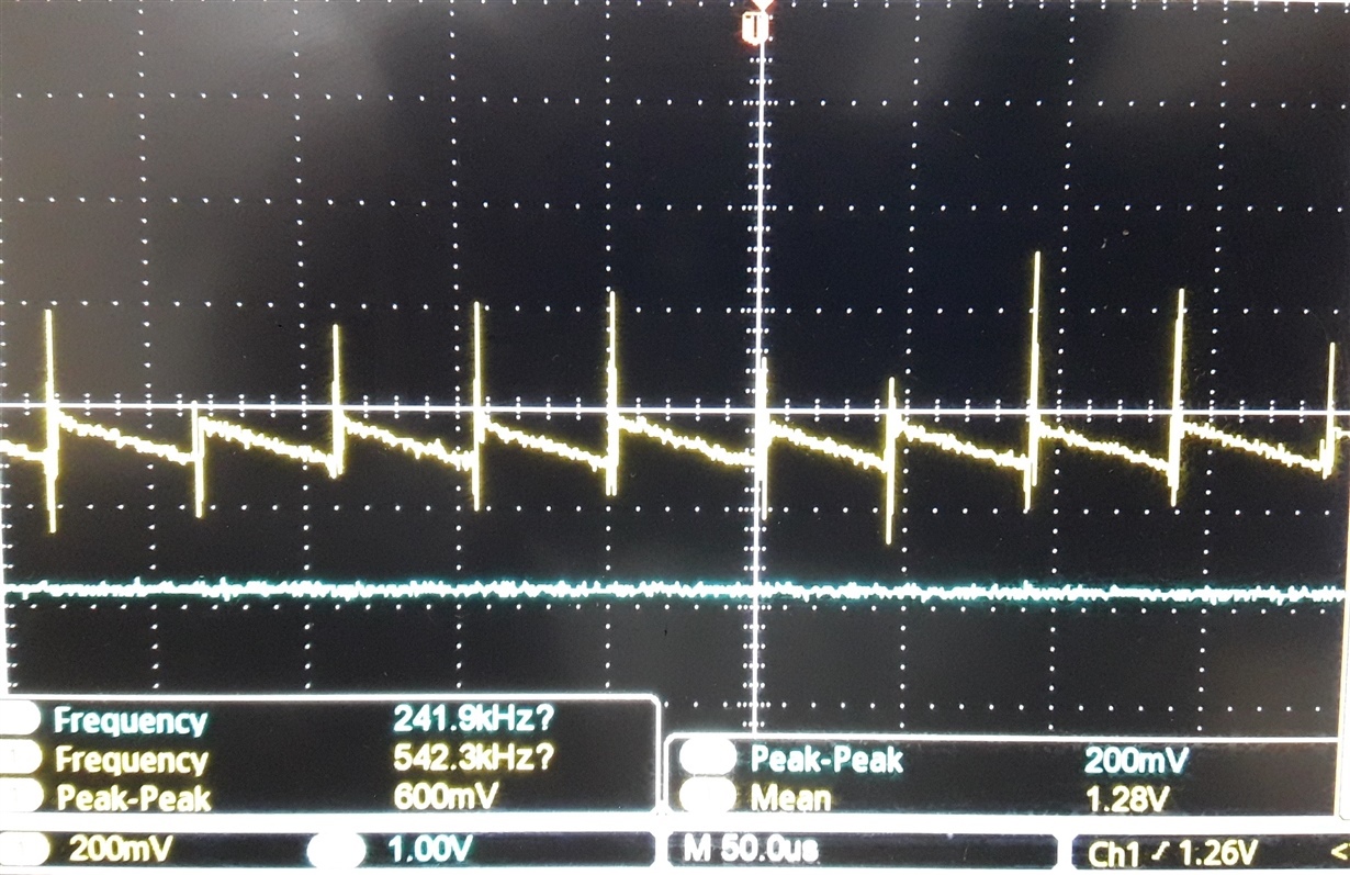
    Vendor Bob past provided the following writing & screen cap.    (that effort hereby applauded!)

    "As you requested, I took an EK-TM4C123GXL Launchpad and removed the four filter capacitors on the LDO, C10, C11, C12 and C22. The board continued to operate and run code with the capacitors removed, but the core 1.2V showed a sawtooth waveform."

    That (past) post to which Bob responded:

    e2e.ti.com/.../3270821