Other Parts Discussed in Thread: TM4C123GH6PM,
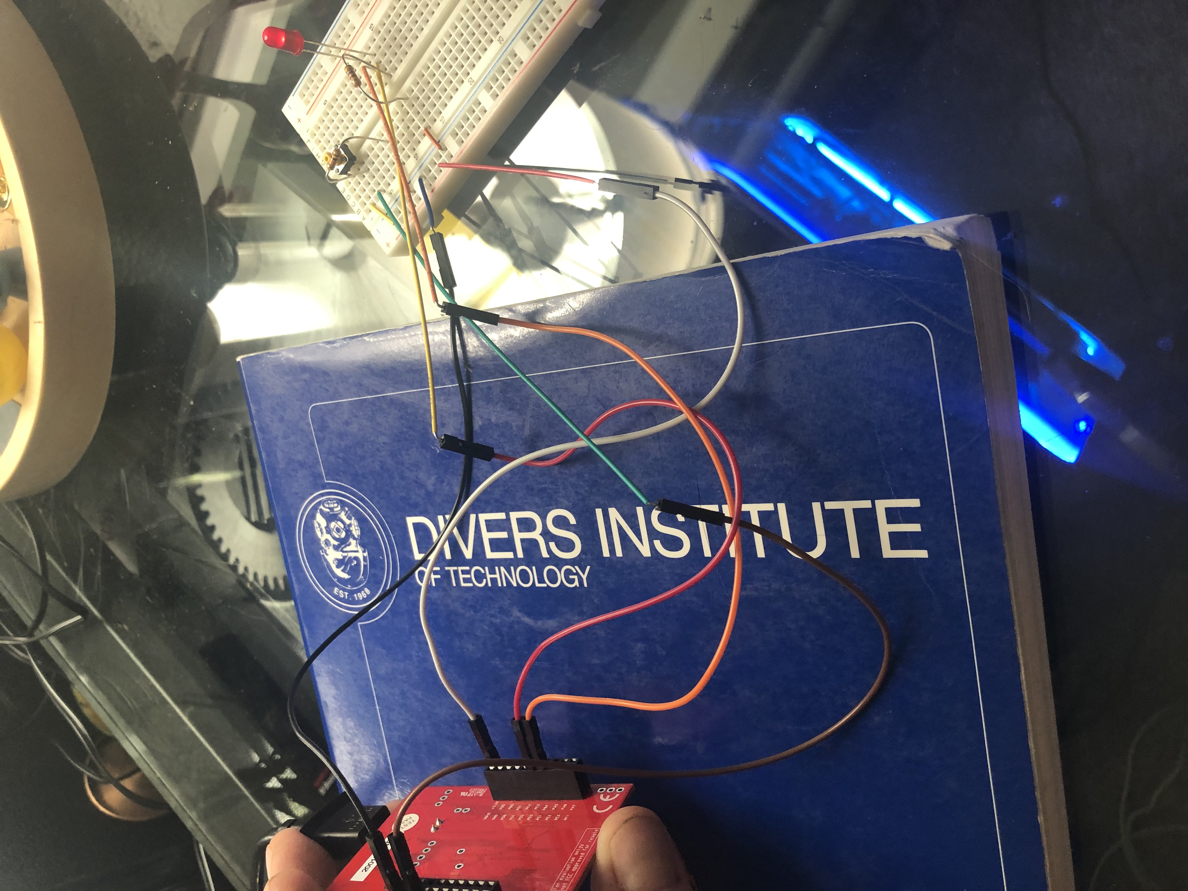
Hello, I am currently exploring some blinking LED code and am having trouble with error message Abort:Input port clock is off. I am confused as to why it will run on the simulator and on the real board but will not execute when debugging. Any tips or suggestions are appreciated. Thank you.
// ***** 1. Pre-processor Directives Section *****
#define PA2 (*((volatile unsigned long *)0x40004010))
#define PA3 (*((volatile unsigned long *)0x40004020))
#define PA32 (*((volatile unsigned long *)0x40004030))
#define GPIO_PORTA_DATA_R (*((volatile unsigned long *)0x400043FC))
#define GPIO_PORTA_DIR_R (*((volatile unsigned long *)0x40004400))
#define GPIO_PORTA_AFSEL_R (*((volatile unsigned long *)0x40004420))
#define GPIO_PORTA_DEN_R (*((volatile unsigned long *)0x4000451C))
#define GPIO_PORTA_AMSEL_R (*((volatile unsigned long *)0x40004528))
#define GPIO_PORTA_PCTL_R (*((volatile unsigned long *)0x4000452C))
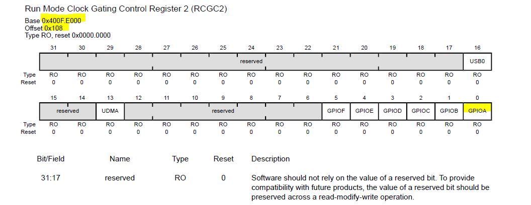
#define SYSCTL_RCGC2_R (*((volatile unsigned long *)0x400FE108))
//#define SYSCTL_RCGC2_GPIO_R (*((volatile unsigned long *)0x00000001)) // port A Clock Gating Control
#include "TExaS.h"
#include "tm4c123gh6pm.h"
void LED_On(void);
void LED_Off(void);
void LED_Init(void);
void EnableInterrupts(void);
void delay(unsigned long halfsecs);
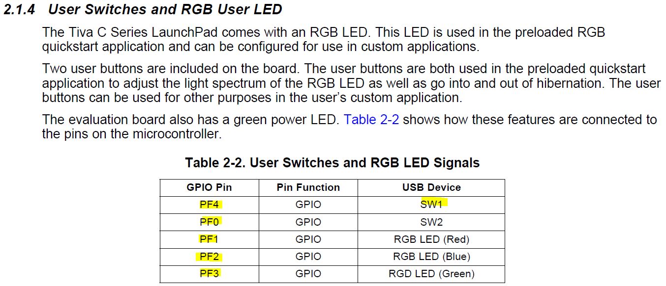
unsigned long SW1;
unsigned long out;
int main(void){
TExaS_Init(SW_PIN_PE0, LED_PIN_PE1, ScopeOn); // activate grader and set system clock to 80 MHz
EnableInterrupts(); // enable interrupts for the grader
LED_Init();// initialize PA2 and make it output
while(1){
LED_On(); // c) LED signal goes low
do {
PA2 = GPIO_PORTA_DATA_R&0x10;
}while(PA2 == 0x00); // b) wait for switch to be pressed (zero means SW1 is pressed
LED_Off();
delay(1);
LED_On();
delay(1);
//LED_Off();
//delay(1);
if (PA2 == 0x10)
{LED_On();
}
}
}
// Subroutine to delay in units of half seconds
void delay(unsigned long halfsecs){
unsigned long count;
while(halfsecs > 0 ) { // repeat while there are still halfsecs to delay
count = 1600000; // 400000*0.5/0.13 that it takes 0.13 sec to count down to zero (1638400)
while (count > 0) {
count--;
} // This while loop takes approximately 3 cycles
halfsecs--;
}
}
// Make PA2 high
void LED_On(void){
GPIO_PORTA_DATA_R |= 0x08;
}
// Make PA2 low
void LED_Off(void){
GPIO_PORTA_DATA_R &= ~0x08;
}
// Make PA2 an output, enable digital I/O, ensure alt. functions off
void LED_Init(void){ volatile unsigned long delay;
SYSCTL_RCGC2_R |= 0x00000001; // 1) activate clock for Port A
delay = SYSCTL_RCGC2_R; // allow time for clock to start
// 2) no need to unlock PA2
GPIO_PORTA_PCTL_R &= ~0x00000F00; // 3) regular GPIO
GPIO_PORTA_AMSEL_R &= ~0x04; // 4) disable analog function on PA2
GPIO_PORTA_DIR_R |= ~0x04; // 5) set direction to output
GPIO_PORTA_AFSEL_R &= ~0x04; // 6) regular port function
GPIO_PORTA_DEN_R |= 0x8C; // 7) enable digital port
}