This thread has been locked.

If you have a related question, please click the "Ask a related question" button in the top right corner. The newly created question will be automatically linked to this question.

CCS/EK-TM4C129EXL: TM4c129EXL launch pad

Part Number: EK-TM4C129EXL

Tool/software: Code Composer Studio

Dear Sir,

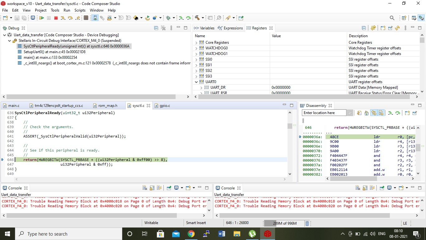
I have problem during debugging. During step execution I had problem when execute this line GPIOPinConfigure(GPIO_PA0_U0RX) ,after that execution jump into infinite loop in startup program.

which I given below...

/ This is the code that gets called when the processor receives a fault
// interrupt. This simply enters an infinite loop, preserving the system state
// for examination by a debugger.
//
//*****************************************************************************
static void
FaultISR(void)
{
//
// Enter an infinite loop.
//
while(1)
{
}
}

And my code is ---


#include <stdint.h>
#include <stdbool.h>
#include <string.h>
#include "inc/hw_ints.h"
#include "inc/hw_memmap.h"
#include "driverlib/debug.h"
#include "driverlib/gpio.h"
#include "driverlib/pin_map.h"
#include "driverlib/sysctl.h"
//#include "driverlib/systick.h"
#include "driverlib/rom.h"
#include "driverlib/rom_map.h"
#include "driverlib/uart.h"
#include "driverlib/interrupt.h"
#include "utils/uartstdio.h"

void SetupUart0(void);
char Uart0_receiver(void);
void UART5_Transmitter(unsigned char data);


void SetupUart0(void)
{
#if defined(TARGET_IS_TM4C129_RA0) || \
defined(TARGET_IS_TM4C129_RA1) || \
defined(TARGET_IS_TM4C129_RA2)
uint32_t ui32SysClockFreqHz;
#endif
uint32_t SysClockFreqHz;
SysClockFreqHz = MAP_SysCtlClockFreqSet((SYSCTL_XTAL_25MHZ | SYSCTL_OSC_MAIN | SYSCTL_USE_PLL | SYSCTL_CFG_VCO_480), 120000000);

//
// Enable GPIO port A which is used for UART0 pins.
// TODO: change this to whichever GPIO port you are using.
SysCtlPeripheralEnable(GPIO_PORTA_BASE);

//
// Enable UART0 so that we can configure the clock.
//

GPIOPinConfigure(GPIO_PA0_U0RX);
GPIOPinConfigure(GPIO_PA1_U0TX);

SysCtlPeripheralEnable(SYSCTL_PERIPH_UART0);
while (SysCtlPeripheralReady(SYSCTL_PERIPH_UART0) != true)
{
}

//
// Configure the pin muxing for UART0 functions on port A0 and A1.
// This step is not necessary if your part does not support pin muxing.
// TODO: change this to select the port/pin you are using.
//
//GPIOPinConfigure(GPIO_PA0_U0RX);
//GPIOPinConfigure(GPIO_PA1_U0TX);

//GPIOPinTypeUART(GPIO_PORTA_BASE, GPIO_PIN_0 | GPIO_PIN_1);

// Sets the configuration of a UART

UARTConfigSetExpClk(UART0_BASE, SysClockFreqHz, 115200, (UART_CONFIG_PAR_NONE | UART_CONFIG_STOP_ONE | UART_CONFIG_WLEN_8));

// Set UART to interrupt when Tx FIFO is almost empty or any char received
UARTFIFOEnable(UART0_BASE);
//UARTFIFOLevelSet(UART0_BASE, UART_FIFO_TX1_8, UART_FIFO_RX1_8);

//Enable Uart
UARTEnable(UART0_BASE);

// IntEnable(INT_UART0);
// UARTIntEnable(UART0_BASE, UART_INT_RX | UART_INT_RT | UART_INT_TX);
UARTStdioConfig(0, 115200, 40000000);

}


/*void Uart0InterruptHandler(void)
{
uint32_t InterruptFlags;

InterruptFlags = UARTIntStatus(UART0_BASE, false);
UARTIntClear(UART0_BASE, InterruptFlags);

if (InterruptFlags & UART_INT_TX)
{
// Room in Tx FIFO
while (UARTSpaceAvail(UART0_BASE))
{
// UARTCharPutNonBlocking(UART0_BASE, BufGet(&Tx));
}
}

if (InterruptFlags & (UART_INT_RX | UART_INT_RT))
{
// Data in Rx FIFO
while (UARTCharsAvail(UART0_BASE))
{
// BufPut(&Rx, UARTCharGetNonBlocking(UART0_BASE));
}
}
} */
// char receive function

char Uart0_receiver(void)
{
char data;
while(UARTCharsAvail(UART0_BASE)!=false)
{
data=UARTCharGet(UART0_BASE);
}
return (unsigned char) data;
}


void UART5_Transmitter(unsigned char data)
{
// unsigned char peta;
while(UARTSpaceAvail(UART0_BASE)!=false)
{
UARTCharPut(UART0_BASE, data);
}
}


/**
* main.c
*/
int main(void)
{
SetupUart0();
UARTprintf("test");

//return 0;
}

Please help me. How can I solve this? Actually I was testing a character(A) send in board (like interrupt ) and it will be on led. When  I will send B then it will be off led.

Imtiaj Hossain


  • I suspect your problem is that you executed the "GPIOPinConfigure(GPIO_PA0_U0RX);" immediately after enabling port GPIOA and did not give enough time for the port to be ready. You can add a while loop to wait for GPIOA to be ready.

        SysCtlPeripheralEnable(SYSCTL_PERIPH_GPIOA);
        while(!SysCtlPeripheralReady(SYSCTL_PERIPH_GPIOA))
        {
        }
        GPIOPinConfigure(GPIO_PA0_U0RX);
        GPIOPinConfigure(GPIO_PA1_U0TX);
    

    Or, you can simply change the order of the code to allow time between enabling the port and accessing it.

        //
        // Enable the GPIO Peripheral used by the UART.
        //
        ROM_SysCtlPeripheralEnable(SYSCTL_PERIPH_GPIOA);
    
        //
        // Enable UART0
        //
        ROM_SysCtlPeripheralEnable(SYSCTL_PERIPH_UART0);
    
        //
        // Configure GPIO Pins for UART mode.
        //
        ROM_GPIOPinConfigure(GPIO_PA0_U0RX);
        ROM_GPIOPinConfigure(GPIO_PA1_U0TX);
        ROM_GPIOPinTypeUART(GPIO_PORTA_BASE, GPIO_PIN_0 | GPIO_PIN_1);
    

  • Dear Bob Sir,

    Sorry for that actually  in Setup Uart0 I did it (). But the problem did not resolve. Please so this part is it correct?


    void SetupUart0(void)
    {
    #if defined(TARGET_IS_TM4C129_RA0) || \
    defined(TARGET_IS_TM4C129_RA1) || \
    defined(TARGET_IS_TM4C129_RA2)
    uint32_t ui32SysClockFreqHz;
    #endif
    uint32_t SysClockFreqHz;
    SysClockFreqHz = MAP_SysCtlClockFreqSet((SYSCTL_XTAL_25MHZ | SYSCTL_OSC_MAIN | SYSCTL_USE_PLL | SYSCTL_CFG_VCO_480), 120000000);

    //
    // Enable GPIO port A which is used for UART0 pins.
    // TODO: change this to whichever GPIO port you are using.
    SysCtlPeripheralEnable(GPIO_PORTA_BASE);

    //
    // Enable UART0 so that we can configure the clock.
    //

    SysCtlPeripheralEnable(SYSCTL_PERIPH_UART0);
    while (!SysCtlPeripheralReady(SYSCTL_PERIPH_GPIOA))
    {
    }

    //
    // Configure the pin muxing for UART0 functions on port A0 and A1.
    // This step is not necessary if your part does not support pin muxing.
    // TODO: change this to select the port/pin you are using.
    //
    GPIOPinConfigure(GPIO_PA0_U0RX);
    GPIOPinConfigure(GPIO_PA1_U0TX);

    //GPIOPinTypeUART(GPIO_PORTA_BASE, GPIO_PIN_0 | GPIO_PIN_1);

    // Sets the configuration of a UART

    UARTConfigSetExpClk(UART0_BASE, SysClockFreqHz, 115200, (UART_CONFIG_PAR_NONE | UART_CONFIG_STOP_ONE | UART_CONFIG_WLEN_8));

    // Set UART to interrupt when Tx FIFO is almost empty or any char received
    UARTFIFOEnable(UART0_BASE);
    //UARTFIFOLevelSet(UART0_BASE, UART_FIFO_TX1_8, UART_FIFO_RX1_8);

    //Enable Uart
    UARTEnable(UART0_BASE);

    // IntEnable(INT_UART0);
    // UARTIntEnable(UART0_BASE, UART_INT_RX | UART_INT_RT | UART_INT_TX);
    UARTStdioConfig(0, 115200, 40000000);

    }

    Execution don't come out from 

    (while (!SysCtlPeripheralReady(SYSCTL_PERIPH_GPIOA))
    {
    } ) this loop.

    I got some like that

    CORTEX_M4_0: GEL Output:
    Memory Map Initialization Complete
    CORTEX_M4_0: Trouble Reading Memory Block at 0x4000c000 on Page 0 of Length 0x4: Debug Port error occurred.
    CORTEX_M4_0: Trouble Reading Memory Block at 0x4000c004 on Page 0 of Length 0x4: Debug Port error occurred.
    CORTEX_M4_0: Trouble Reading Memory Block at 0x4000c004 on Page 0 of Length 0x4: Debug Port error occurred.
    CORTEX_M4_0: Trouble Reading Memory Block at 0x4000c018 on Page 0 of Length 0x4: Debug Port error occurred.
    CORTEX_M4_0: Trouble Reading Memory Block at 0x4000c020 on Page 0 of Length 0x4: Debug Port error occurred.

    How can I resolve this issue.

    Yours faithfully

    Imtiaj

  • Actually, there are several things wrong with your code. It looks like you took a working example and made changes. When that did not work, you made more changes. 

    The first thing wrong is you used the wrong parameter when you enabled the clocks to GPIOA. It should be:

        SysCtlPeripheralEnable(SYSCTL_PERIPH_GPIOA);
    

    Not:

    SysCtlPeripheralEnable(GPIO_PORTA_BASE);

    You have several unnecessary UART calls, but then call UARTStdioConfig() with the wrong frequency value.

    I suggest you go back to this example in TivaWare and start from there.

    C:\ti\TivaWare_C_Series-2.2.0.295\examples\boards\ek-tm4c129exl\hello