This thread has been locked.

If you have a related question, please click the "Ask a related question" button in the top right corner. The newly created question will be automatically linked to this question.

MSP432P401R: TIMER A0 and A1 SYNCHRONIZATION

Part Number: MSP432P401R

Is there a way to specific way to synchronize two different Timers such and Timer A0 and A1?  Or just using the same clock source should automatically synchronize the timers?

Or why do two Timers A0 and A1 set to different counting modes Timer A0 in Up/Down mode and Timer A1 in Up mode not operate synchronized even though they are fed by the same clock?

#include "msp.h"
#include <stdio.h>

int period = 120; // Period of Timer
int period2 = 240;

void main(void)
{
	WDT_A->CTL = WDT_A_CTL_PW | WDT_A_CTL_HOLD;		// stop watchdog timer

	__disable_irq();

       P7->SEL0 |=  0b00001000;
       P7->SEL1 &= ~0b00001000;    // configure P7.3 as alt 1 module function
       P7->DIR  |=  0b00001000;    // make P7.3 out

       P8->SEL0 &= ~0b00000001;
       P8->SEL1 |=  0b00000001;    // configure P8.0 as alt 2 module function
       P8->DIR  |=  0b00000001;    // make P8.0 out

       PJ->SEL0 |= BIT2 | BIT3;
       PJ->SEL1 &= ~(BIT2 | BIT3);

       CS->KEY = CS_KEY_VAL;        // Set External Crystal 48MHZ
         CS->CTL2 |= CS_CTL2_HFXT_EN | CS_CTL2_HFXTFREQ_6;
         while(CS->IFG & CS_IFG_HFXTIFG)
         CS->CLRIFG |= CS_CLRIFG_CLR_HFXTIFG;
       CS->CTL1 &= ~(CS_CTL1_SELS_MASK | CS_CTL1_DIVS_MASK);
       CS->CTL1 |= CS_CTL1_SELS_5;
       CS->CTL1 |= CS_CTL1_DIVS_1;   // Divide SMCLK /2  = 24MHz
       CS->KEY = 0;


    TIMER_A0->CTL = TIMER_A_CTL_TASSEL_2 | TIMER_A_CTL_MC__UPDOWN |  TIMER_A_CTL_CLR; // SMCLK, Up/Down mode, Clear TAR
//  TIMER_A1->CTL = TIMER_A_CTL_TASSEL_2 | TIMER_A_CTL_MC__UP |  TIMER_A_CTL_CLR; // SMCLK, Up/Down mode,  Clear TAR
    TIMER_A1->CTL = TIMER_A_CTL_TASSEL_2 | TIMER_A_CTL_MC__UP |  TIMER_A_CTL_CLR; // SMCLK, Up,           Clear TAR

    TIMER_A0->CCTL[0] = TIMER_A_CCTLN_OUTMOD_4;         // CCR0 toggle         P7.3
    TIMER_A1->CCTL[0] = TIMER_A_CCTLN_OUTMOD_4;         // CCR0 toggle         P8.0

    TIMER_A0->CCR[0] = period;  // TACCR_0 Register Value  This is the period compare
//    TIMER_A1->CCR[0] = period;  // TACCR_0 Register Value  This is the period compare
    TIMER_A1->CCR[0] = period2;  // TACCR_0 Register Value  This is the period compare

    __enable_irq();              /* global enable interrupt */

	while (1) {
	}
}

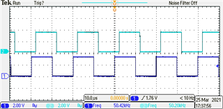
In above code when I use the commented out lines and set both Timers exactly the same the outputs are synchronized.

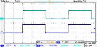
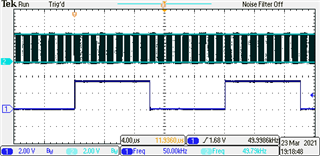
Then if I set Timer A1 to Up mode and double the period so the frequency will be the same as Timer A0 in Up/Down mode, the Timer are no longer synchronized even though both are drive n by the same SMCLK.

  • The two waves aren't synchronized because they're different frequencies. On my scope, neither test condition shows the waves synchronized, though the drift is slower in the first case (probably an illusion).

    To see this you need to compare TRM (SLAU356I) Figs 19-3 and 19-8. A full cycle in Up mode takes (CCR0+1) ticks, so two cycles is 2*CCR0+2. A single cycle in Up/Down mode takes 2*CCR0+1, since it only spends one tick at CCR0.

    So to get the first test condition, replace:

    int period2 = 240;

    with

    int period2 = 240-1;

    and for the second:

    > TIMER_A1->CCR[0] = period;

    becomes

    > TIMER_A1->CCR[0] = period-1;

  • Thanks. Your reply put me on the right track. However, to make the two waveforms synchronize on the scope,

    if period = 120 ticks with SMCLK = 24MHz clock

    the Timer A0 Up/Down CCR[0] = period-1 or 119

    the Timer A1 Up           CCR[0] = (2*period-1) -1 or 238-1       {Still not sure why the extra -1 tick synchronizes the frequency}

    CH1 is Timer A0 Up/Down    CH2 is Timer A1 Up

    Corrected code is

    #include "msp.h"
    #include <stdio.h>
    
    int period = 119; // Period of Timer
    int period2 = 238;
    
    void main(void)
    {
    	WDT_A->CTL = WDT_A_CTL_PW | WDT_A_CTL_HOLD;		// stop watchdog timer
    
    	__disable_irq();
    
           P7->SEL0 |=  0b00001000;
           P7->SEL1 &= ~0b00001000;    // configure P7.3 as alt 1 module function
           P7->DIR  |=  0b00001000;    // make P7.3 out
    
           P8->SEL0 &= ~0b00000001;
           P8->SEL1 |=  0b00000001;    // configure P8.0 as alt 2 module function
           P8->DIR  |=  0b00000001;    // make P8.0 out
    
           PJ->SEL0 |= BIT2 | BIT3;
           PJ->SEL1 &= ~(BIT2 | BIT3);
    
           CS->KEY = CS_KEY_VAL;        // Set External Crystal 48MHZ
             CS->CTL2 |= CS_CTL2_HFXT_EN | CS_CTL2_HFXTFREQ_6;
             while(CS->IFG & CS_IFG_HFXTIFG)
             CS->CLRIFG |= CS_CLRIFG_CLR_HFXTIFG;
           CS->CTL1 &= ~(CS_CTL1_SELS_MASK | CS_CTL1_DIVS_MASK);
           CS->CTL1 |= CS_CTL1_SELS_5;
           CS->CTL1 |= CS_CTL1_DIVS_1;   // Divide SMCLK /2  = 24MHz
           CS->KEY = 0;
    
    
        TIMER_A0->CTL = TIMER_A_CTL_TASSEL_2 | TIMER_A_CTL_MC__UPDOWN |  TIMER_A_CTL_CLR; // SMCLK, Up/Down mode, Clear TAR
    //    TIMER_A1->CTL = TIMER_A_CTL_TASSEL_2 | TIMER_A_CTL_MC__UPDOWN |  TIMER_A_CTL_CLR; // SMCLK, Up/Down mode,  Clear TAR
        TIMER_A1->CTL = TIMER_A_CTL_TASSEL_2 | TIMER_A_CTL_MC__UP |  TIMER_A_CTL_CLR; // SMCLK, Up,           Clear TAR
    
        TIMER_A0->CCTL[0] = TIMER_A_CCTLN_OUTMOD_4;         // CCR0 toggle         P7.3
        TIMER_A1->CCTL[0] = TIMER_A_CCTLN_OUTMOD_4;         // CCR0 toggle         P8.0
    
        TIMER_A0->CCR[0] = 119;  // TACCR_0 Register Value  This is the period compare
    //    TIMER_A1->CCR[0] = 119;  // TACCR_0 Register Value  This is the period compare
        TIMER_A1->CCR[0] = 238-1;  // TACCR_0 Register Value  This is the period compare
    
        __enable_irq();              /* global enable interrupt */
    
    	while (1) {
    	}
    }

  • A single cycle in Up/Down mode takes 2*CCR0+1

    I was mistaken. A single cycle in Up/Down mode takes 2*CCR0 ticks.  It counts from 0..CCR0-1 [CCR0 ticks] followed by CCR0..1 [CCR0 ticks]. Then it counts to 0, which is part of the next cycle. (I counted 0 twice before.) Thanks for catching that.